Optical curing apparatus

a curing apparatus and optical technology, applied in the field of optical curing apparatus, can solve the problems of inability to apply the operation originally designed, the rim cannot be removed for this purpose, and the medical practice flaw, so as to increase the hygienic quality of the medical field

Active Publication Date: 2006-08-29
WANG SHU LUNG
View PDF7 Cites 36 Cited by
  • Summary
  • Abstract
  • Description
  • Claims
  • Application Information

AI Technical Summary

Benefits of technology

[0005]The primary object of the invention is to provide an optical curing apparatus that has a front shell body which consists of a first shell and a second shell that are detachable and turnable relative to each other, and are coupled by screwing. The first shell and the second shell may be turned 360 degrees relative to each other so that the angle of the light channeling member may be adjusted as required. As the light channeling member and the first shell are detachable, they may be adapted to the light channeling members of various sizes, and may be removed for sterilizing, or become a disposable item to increase medical hygienic quality.

Problems solved by technology

While the light channeling member may be detached for sterilizing, the case rim cannot be removed for this purpose.
This is a serious flaw of medical practice that has to be resolved immediately.
The operation originally designed cannot be applied.
It is not convenient to use.
This hinders interchangeable function.
This increases the cost of medical equipment and results in waste.
It also makes carrying difficult, and needs a larger storage space.
In addition, the radiation member in the conventional optical curing apparatus is an important element and quite expensive.
Heat of the radiation member directly transfers to the plastic case and could results in brittle or deformation of the case, and make the apparatus not appealing.
This cannot meet the clean and hygienic requirements in the practice of dentistry.
Moreover, as the radiation member is most expensive element in the whole optical curing apparatus, in the event that the case or other element is damaged, the entire apparatus has to be replaced.
When to replace the battery, the radiation member is difficult to remove.
As the radiation member is expensive, it cannot be thrown away with the battery, hence it creates a lot of problems in maintenance.
To throw the radiation member away with the battery will increase the maintenance cost.

Method used


Image

  • Optical curing apparatus
  • Optical curing apparatus
  • Optical curing apparatus

Examples


Embodiment Construction

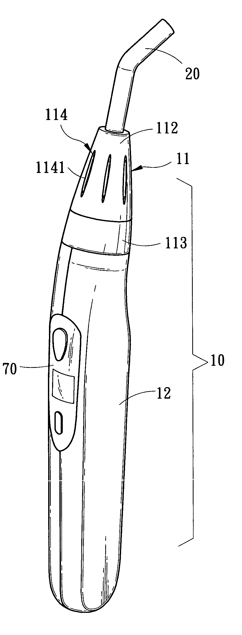
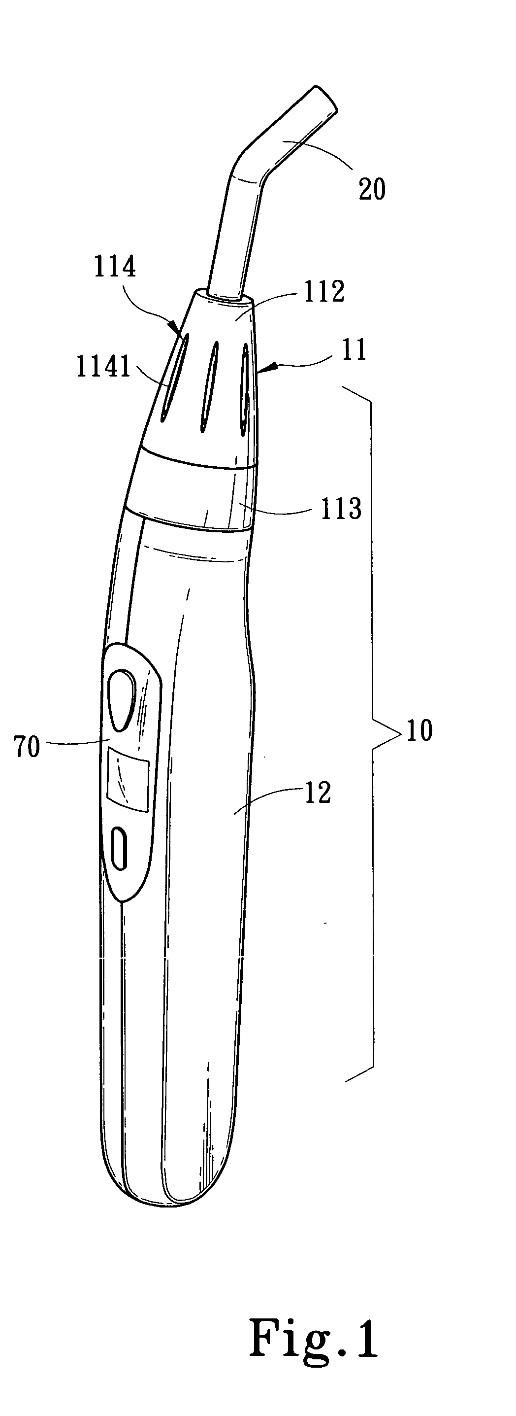
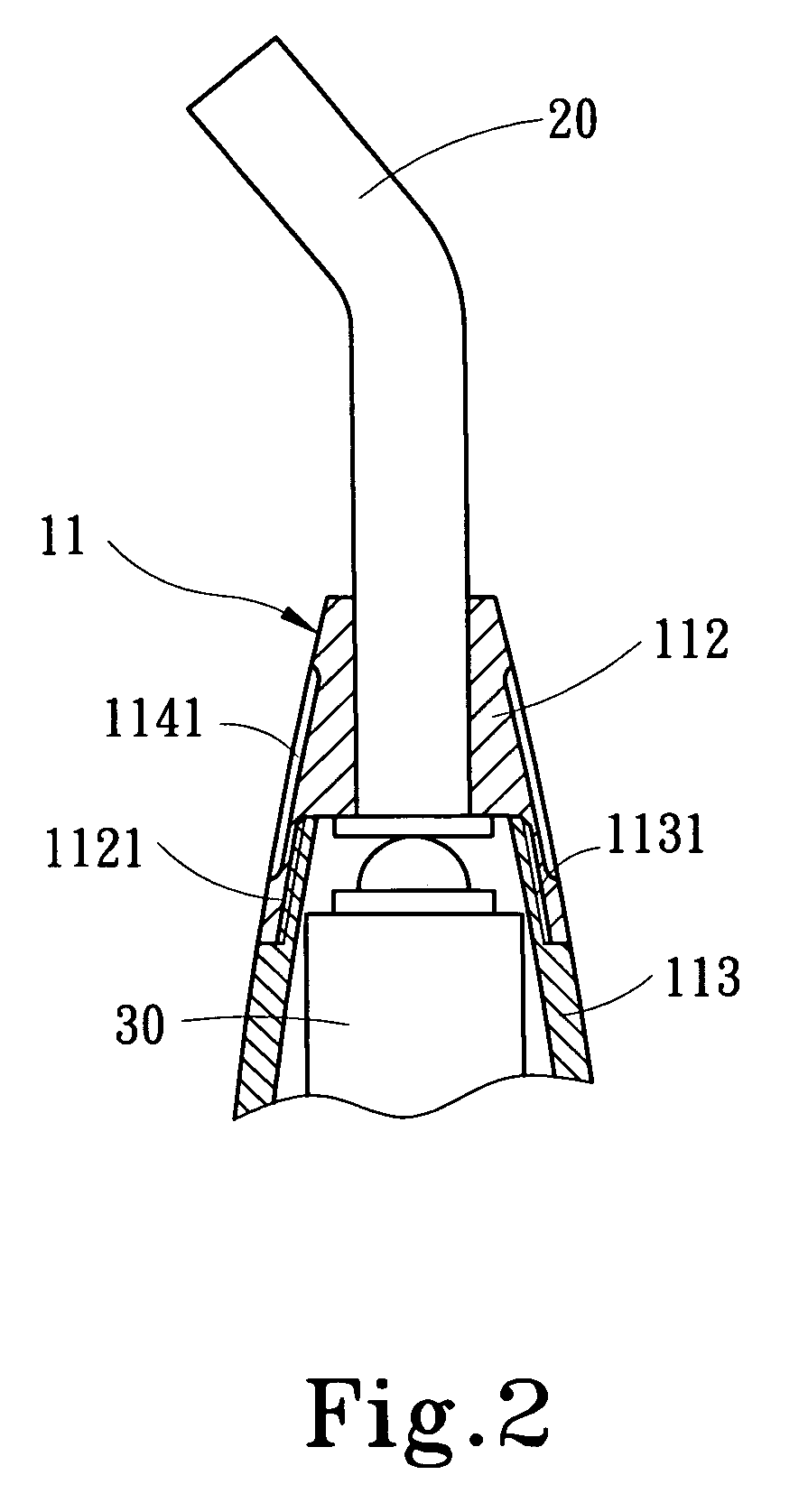
[0016]The optical curing apparatus of the invention mainly aims at curing material used in dentistry. Please referring to FIGS. 1 and 3, the present invention includes:[0017]a case 10 consisting of a front shell body 11 and a rear shell body 12. The front shell body 11 has a housing section 111 and has a front end coupling with a light channeling member 20. The rear shell body 12 is formed with an external shape for user grasping when in use, and has a housing compartment 121 to hold various elements.

[0018]The front shell body 11 is detachable and turnable for 360 degrees. It includes a first shell 112 and a second shell 113. The first shell 112 has internal screw threads 1121 to couple with external screw threads 1131 formed on the second shell 113. Such a screwing design allows the first shell 112 and the second shell 113 to be turnable relative to each other for 360 degrees (referring to FIG. 2). The first shell 112 further has a form an operating section 114 to facilitate turnin...


PUM


Abstract

An optical curing apparatus includes a front shell body which consists of a first shell and a second shell that are coupled in a detachable and turnable manner. A light channeling member is fastened to the first shell and may be adjusted angularly to suit user's requirements. The light channeling member and the first shell are detachable. They are adaptable to the light channeling member of various diameters, and may be removed for sterilizing, or become a disposable and replaceable item. A radiation member and an electric power supply unit are provided and detachably coupled through a connector. The radiation member is reusable even if the case is damage or other elements are breakdown.

Description

FIELD OF THE INVENTION[0001]The present invention relates to an optical curing apparatus and particularly to an apparatus for curing dental material through optical radiation.BACKGROUND OF THE INVENTION[0002]Optical curing dental material is often used by dentists in the curing process, such as bonding or processing a filler in a tooth cavity and cementing the filler on a desired position. As the oral cavity has a limited space for optical curing process, the general optical curing apparatus often includes an elongate and narrow light channeling member such as a bundle of optical fibers with a free end which may be moved close to the optical curing material so that light can be directly projected to the material. U.S. Pat. No. 6,692,251B1 entitled “Apparatus and method for curing materials with light radiation” discloses an apparatus that has a light channeling member removable from the light source so that it may be sterilized for use on different patients. But in practice, not onl...

Claims


Application Information

Patent Timeline
Patent Type & Authority Patents(United States)
IPC IPC(8): G02B6/36A61C3/00F21V5/00A61C13/15G02B6/42
CPCA61C19/004Y10S385/901G02B6/4292G02B6/4201
Inventor WANG, SHU-LUNG
Owner WANG SHU LUNG
Why Eureka
Try Eureka