Socket for electrical parts

a technology for electrical parts and sockets, which is applied in the direction of individual semiconductor device testing, coupling device connection, instruments, etc., can solve the problems of less heat radiation function of heat sinks and large heat sinks, and achieve the effect of enlargement of the ic package in its structur

Active Publication Date: 2006-08-29
ENPLAS CORP
View PDF2 Cites 16 Cited by
  • Summary
  • Abstract
  • Description
  • Claims
  • Application Information

AI Technical Summary

Benefits of technology

[0007]An object of the present invention is accordingly to provide a socket for an electrical part capable of being provided with a large-sized heat sink, hence improving heat radiation performance of the electrical part and widely pressing an upper surface of the electrical part.
[0013]According to the one aspect of the present invention, since the opening and closing timings of the open / close mechanism and the latch member are set such that the latch member is first closed and the open / close mechanism is then closed, there is less possibility, for the open / close mechanism and the latch member, of erroneously carrying out their opening and closing operations, thereby surely performing the opening / closing operation thereof.
[0014]In addition, since the timings are set such that the latch member is first closed and the open / close mechanism is then closed, it is possible for the heat sink provided for the open / close mechanism to have a size capable of covering the latch member, and hence, the heat sink can be constructed in a large size, thus improving the heat radiation function thereof.
[0016]According to the other aspect of the present invention mentioned above, after pressing the peripheral edge portion of the electrical part by the latch member, the open / close mechanism can widely and uniformly press a portion of the electrical part inside the pressing portion of the latch member, so that, even in a case of extremely thin electrical part accommodated in the accommodation portion of the socket body, it is not warped, when pressed against the contact pin, by the reaction force from the contact pin, and the extremely stable pressing can be hence ensured.
[0017]According to the further characteristic feature of the present invention, the open / close mechanism is disposed at one side portion of a rectangular structure of the accommodation portion of the socket body and three latch members are disposed at three side portions of the rectangular structure, so that the heat sink can be formed in an integral structure, not with divided ones, and hence, an area of the contact projection contacting the electrical part can be made larger, thus improving the heat radiation function of the heat sink. That is, for example, if the heat sink is divided into two parts at its central portion, a gap is inevitably caused at its central portion when closed, which will provide an adverse heat radiation function. Moreover, since the contacting area of the contact projection can be made larger, the heat sink can be widely and uniformly contacted to the upper surface of the electrical part, establishing a stable contacting state.
[0019]According to the further characteristic feature of the present invention mentioned above, when the latch member is rotated in its closing direction, the electrical part is pressed and, thereafter, when the latch member is moved in parallel in downward direction, the electrical part is pushed. Therefore, it is possible to locate the rotational shaft of the latch member to a portion in the vicinity of the center of the socket, thus making compact the IC socket. That is, the latch member can be retired from the IC package insertion / take-out area by the outward rotating opening motion and can be moved in parallel in downward direction, thus ensuring the pushing amount or distance of the IC package 12. On the contrary, in a case when the IC package is retired from the IC package insertion / take-out area by entirely rotating the latch member to thereby ensure the IC package pushing amount, it is necessary to separate the rotational shaft from the IC package as much as possible (that is, to locate at a position on the outside of the IC socket), which may result in an enlargement of the IC package in its structure.

Problems solved by technology

According to such requirement, it is difficult to make large the size of the heat sink, resulting in less heat radiation function of the heat sink.

Method used


Image

  • Socket for electrical parts
  • Socket for electrical parts
  • Socket for electrical parts

Examples


Embodiment Construction

[0040]An embodiment of the present invention will be described hereunder.

[0041]FIGS. 1 to 20 represents one preferred embodiment of the present invention.

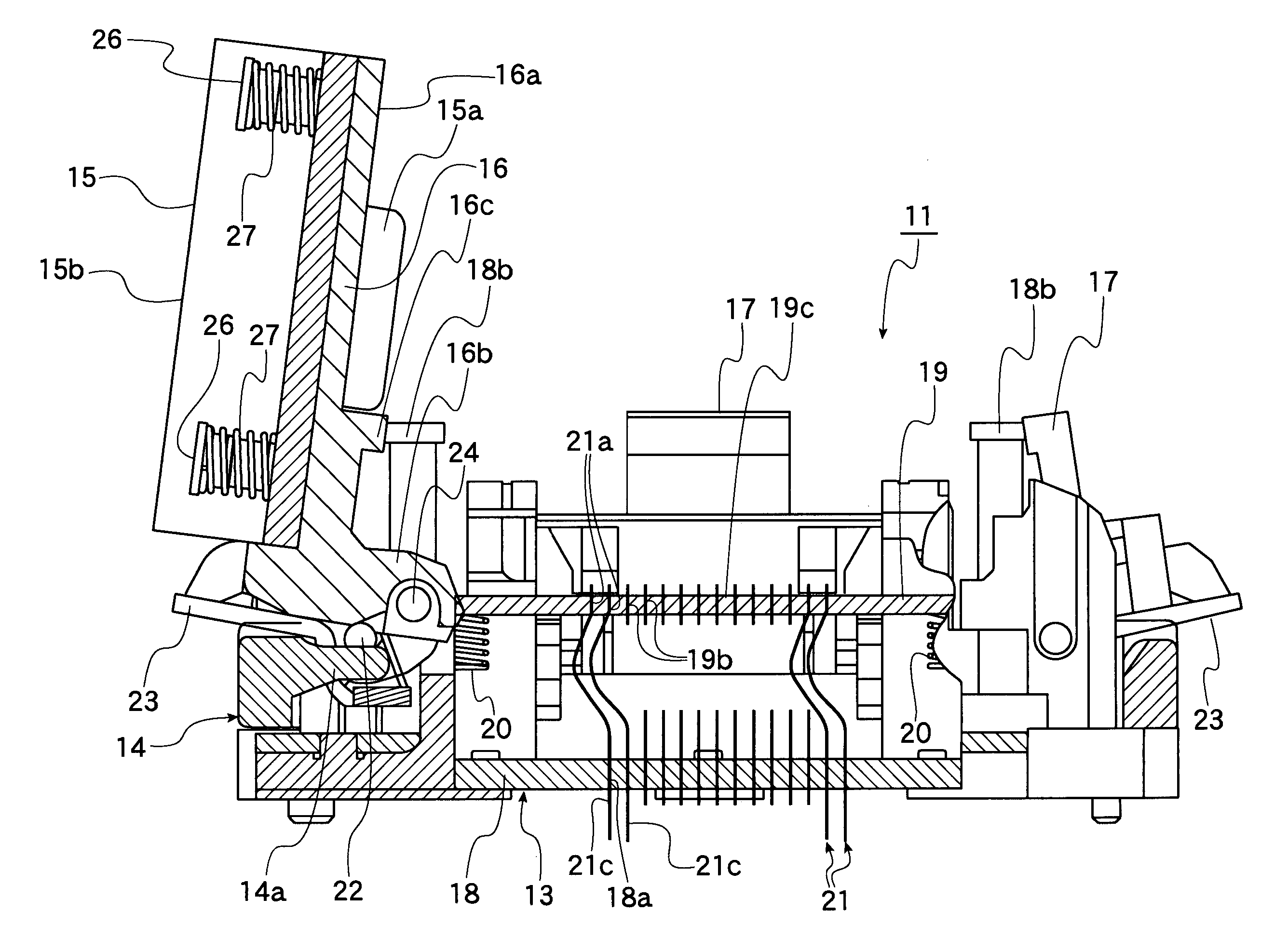
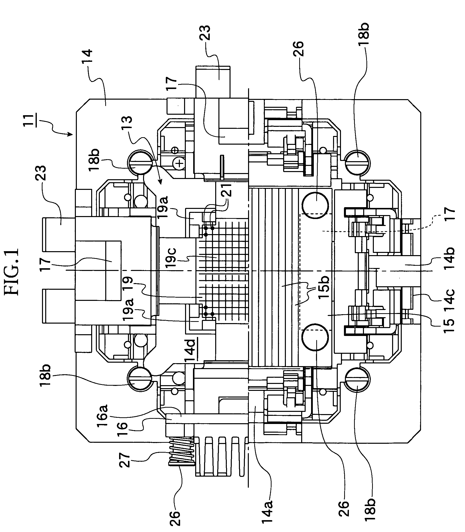
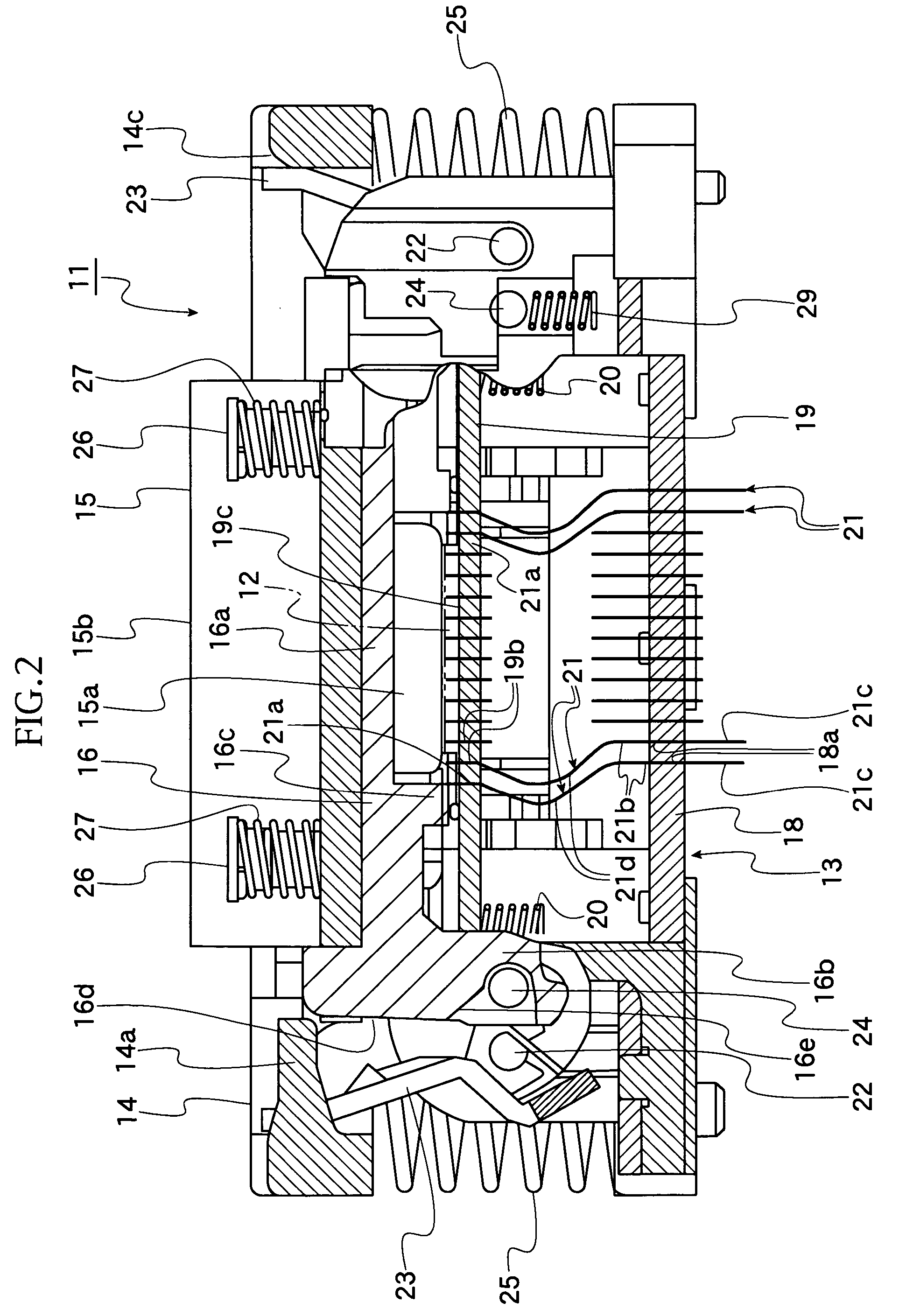
[0042]In a structure of the present invention, a reference numeral 11 denotes an IC socket as “socket for electrical parts”, and the IC socket 11 is a member for establishing an electrical connection between a terminal 12b of an IC package 12, as the electrical part, and a circuit board, not shown, of a measuring device such as tester for carrying out a performance test of the IC package 12.

[0043]The IC package 12 has, as shown in FIGS. 19 and 20, for example, substantially square package body 12a having a bottom surface on which a number of terminals 12b are formed.

[0044]The IC socket 11 has a socket body 13 which is mounted on a circuit board and to which the IC package 12 is mounted. The socket body 13 is also provided with an operation member 14 to be vertically movable. When the operation member 14 is moved vertically, an open...


PUM


Abstract

A socket for an electrical part of the present invention has a socket body provided with an accommodation portion in which an IC package is accommodated, an open / close mechanism having a heat sink for performing radiation of heat of the IC package accommodated on the socket body, and a latch member for pressing the IC package accommodated on the socket body, in which opening and closing timings of the open / close mechanism and the latch member are set such that the latch member is first closed and the open / close mechanism is thereafter closed.

Description

BACKGROUND OF THE INVENTION[0001]1. Field of the Invention[0002]The present invention relates to a socket for an electrical part holding an electrical part such as semiconductor device (called hereinlater “IC package”) or like and provided with an open / close mechanism abutting against an upper surface of such electrical part so as to widely press the same.[0003]2. Prior Art of the Invention[0004]One example of a socket of the kind mentioned above is disclosed in Japanese Laid-Open Patent Publication No. 2000-113954, in which a socket includes a socket body to which an IC mount space is formed and a contact to be electrically connected to an IC package mounted to the IC mount space.[0005]The socket body is also provided with a pressing member to be rotatable, and a heat sink is provided for the pressing member for performing heat radiation through contacting to the IC package. After the IC package is pressed by the pressing member, this pressing member is pressed by a latch so as to ...

Claims


Application Information

Patent Timeline
Patent Type & Authority Patents(United States)
IPC IPC(8): H01R13/62G01R31/26G01R1/04G01R1/073H01R13/24H01R33/76
CPCH01R13/2435G01R1/0466
Inventor HAYAKAWA, KENJIHIRAIWA, HIROYUKI
Owner ENPLAS CORP
Why Eureka
Try Eureka