Vehicular structural members and method of making the members

a technology of structural members and vehicles, applied in the field of light weight inserts, can solve the problems of rigidity of structural members, unpredictability and variability of crash worthiness of one automobile to another, and have not been used for improving, so as to achieve the effect of easy identification and easy insertion

Active Publication Date: 2006-08-29
DOW GLOBAL TECH LLC
View PDF182 Cites 33 Cited by
  • Summary
  • Abstract
  • Description
  • Claims
  • Application Information

AI Technical Summary

Benefits of technology

[0009]Objects of this invention include, but are not limited to; (1) a method of inserting a rigid foam into a hollow member of a vehicle, such that the foam is precisely located within the hollow member, (2) a method of easily determining the presence of the foam within the hollow member, (3) a prefoamed insert that may be easily inserted into the hollow member and subsequently bound to the hollow member during E-coating heating, while not becoming adhesively bound during the formation (e.g., welding) of the hollow member, (4) a method of inserting a foam into a hollow member that does not plug up functional holes in the wall of the hollow member and (5) a method of forming channels between the foam and walls of the hollow member that can be used for drainage of the E-coating and also for conduits for mounting other vehicle hardware, such as brake lines or wires.
[0015]The present invention allows the insertion of a rigid foam part precisely within a vehicular hollow member, while also making it easier to determine in production that the foam is present within the hollow member (i.e., observation of the pin). The method of the invention is particularly useful in forming a structural body of a vehicle, such as the automobile frame rail. For example, it is quite common for frame rails of automobiles to have sections that are weakened to create crush zones to dissipate the energy of an accident and protect the occupants. The frame rails also support parts of the automobile like the transmission. The method allows for foam, such as polyurethane foam, to be introduced selectively into the frame rail without compromising the crush zone or clogging the mounting holes for other components, such as engines and transmission. The method may also be used to make other components of a vehicle, such as rocker panels, beams, pillars, crossbars, body mounts and the like. The method may also be used for other applications, such as athletic equipment, boats, bicycles, aircraft, trucks and trains.

Problems solved by technology

Because foams have been difficult to locate precisely and contain within a certain area of a hollow structural member, from one vehicle to another, they have not been used for improving, for example, the rigidity of structural members.
This inability to know exactly where the foam is and to what extent the foam fills the cavity leads to unpredictability and variability of the crash worthiness of one automobile to another.
For example, crush zones designed into the structural member may contain unwanted foam resulting in excessive energy being delivered to a vehicle occupant in an accident, whereas a foam that does not sufficiently fill the cavity could result in a similar problem.
This uncontrolled foaming and filling of the cavities also leads to problems, such as foam escaping and clogging up functional holes, such as mounting holes for other components.
Another problem is that if the foam is inserted in the manufacturing process and later foamed by the application of heat during E-coating, the foam may be foamed by the welding process used to make the cavity.
Each of these prior art methods fail to address the problem of precisely locating and positioning the foam within the hollow member.
In addition, they fail to address the problem of the foam plugging up holes in the hollow member used for mounting other items to the member or leaving pathways within the member for other items, such as wires that are accessible after the foam has been introduced into the hollow member.

Method used


Image

  • Vehicular structural members and method of making the members
  • Vehicular structural members and method of making the members
  • Vehicular structural members and method of making the members

Examples


Embodiment Construction

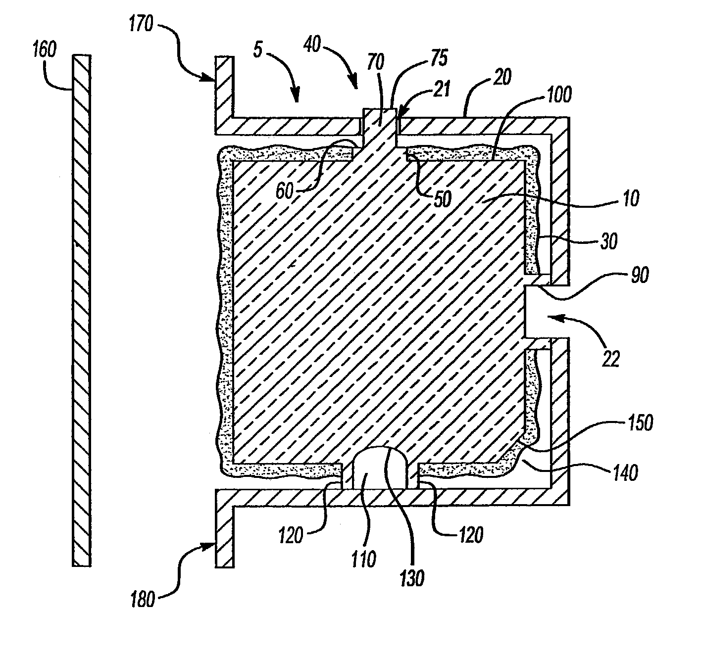
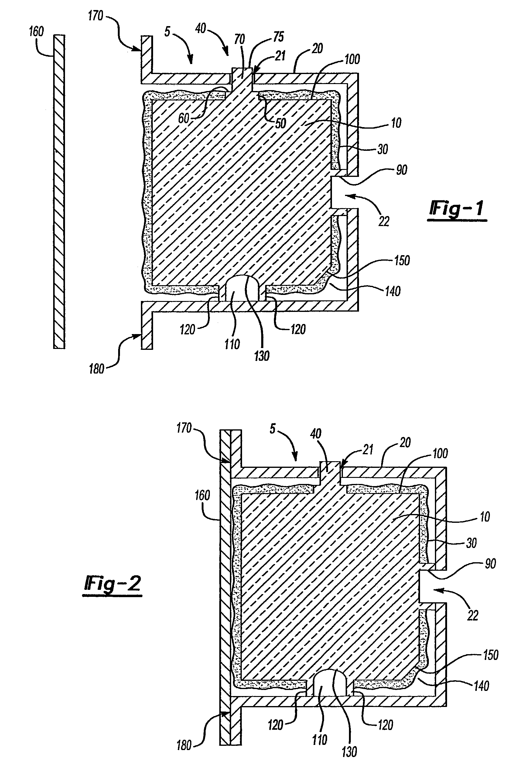
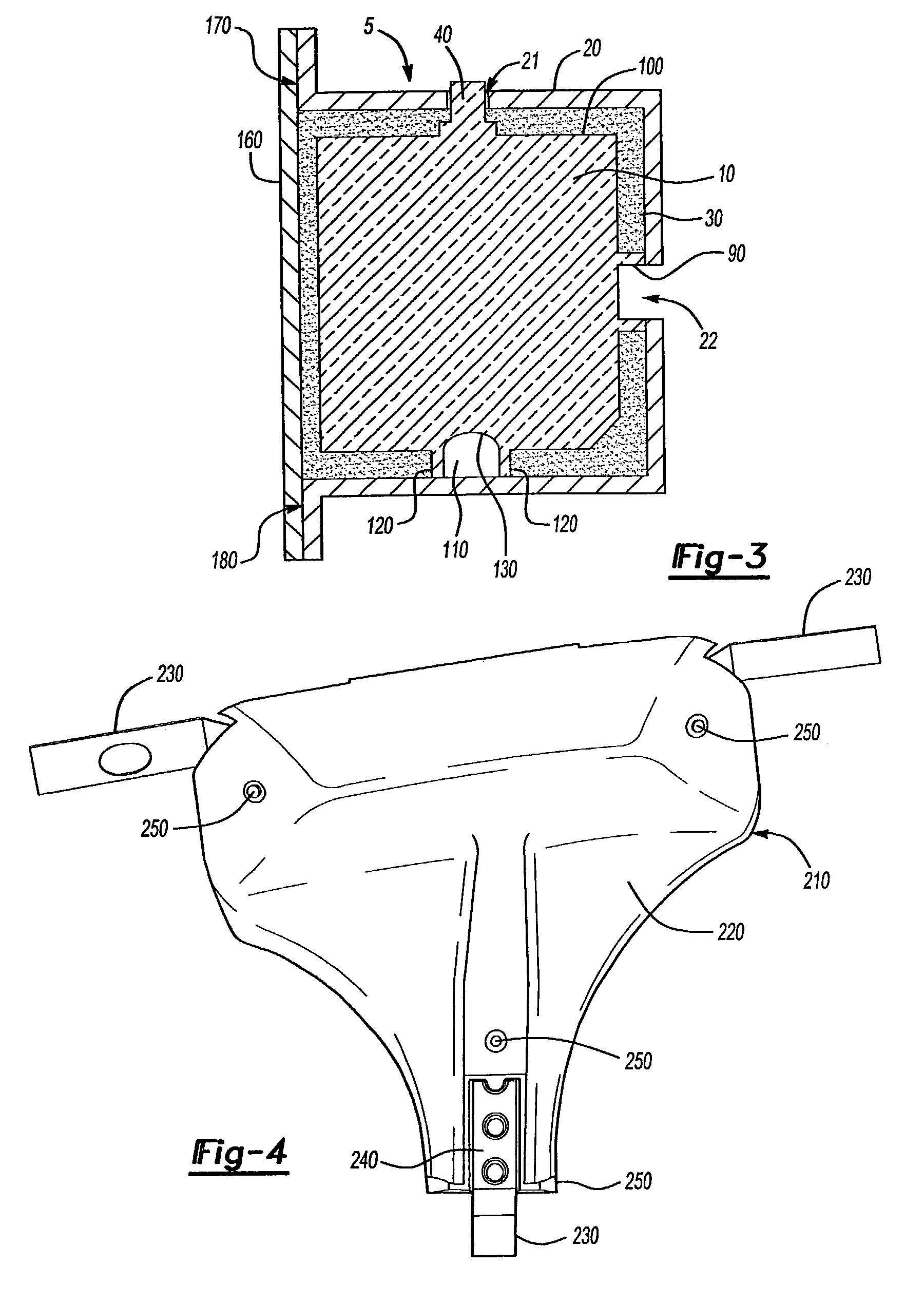
[0021]Hollow member as used herein means an empty cavity formed by the parts of the apparatus, such as an automobile, which cavity is typically enclosed. The apparatus may exhibit structural weakness at the point of the location of the hollow member. At least a portion with respect to the location of the adhesive on the shaped foam article means that the shaped foam article has adhesive on some or all of its outer surface. Integral locating means is a means for locating and holding the shaped part in the location it is meant to be placed wherein the locating means is integrated into the shaped part. The integral locating means can be a shaped indentation or protrusion made from the foam used to form the shaped part. Alternatively, the integral locating means is made of another material wherein a portion of the locating means is molded into the shaped foam part or permanently affixed post molding so as to permanently lock the integral locating means in place. The integral locating me...


PUM

PropertyMeasurementUnit
densityaaaaaaaaaa
densityaaaaaaaaaa
temperatureaaaaaaaaaa

Abstract

The present invention is an article comprising a shaped rigid foam part; a heat activated foamable adhesive applied directly to at least a portion of the outer surface of the shaped foam part and an integral locating means. A second aspect of the invention is a method of forming a foam filled vehicle hollow member comprising, (a) inserting into a vehicular hollow member a rigid foam part comprised of a rigid foam having a heat activated foamable adhesive on at least a portion of the rigid foam insert and at least one integral locating means extending from a surface of the rigid foam, (b) engaging the locating means with the hollow member to locate the rigid foam part within the hollow member, and (c) heating the hollow member having the rigid foam part therein to a temperature and for a time sufficient to activate the heat activated expandable adhesive to form the foam filled vehicle hollow member.

Description

[0001]This application claims the benefit of U.S. Provisional application No. 60 / 373,088, filed Apr. 15, 2002.BACKGROUND OF THE INVENTION[0002]The present invention relates to lightweight inserts for improving the structural integrity or dampen the sound of vehicular structural members, such as a car's frame rail or pillar.BACKGROUND[0003]Reducing automotive vehicle weight is and continues to be important to meet ever more stringent fuel economy and environmental standards. All the while, automobiles are expected to be quieter and safer. To meet these contradictory desires, automotive engineers have introduced foams into vehicular cavities to primarily reduce noise (acoustic foams). These foams have generally been introduced into a hollow area of the structural member after the member has been formed. The foam has also been introduced by inserting a foamable material in the hollow member as the member is being formed and subsequently foaming the foamable material during, for example...

Claims


Application Information

Patent Timeline
Patent Type & Authority Patents(United States)
IPC IPC(8): B29C44/06B29C39/10B29C44/18B29C65/48B29C65/56B29K105/04B29L31/30B62D21/02B62D25/04B62D29/00C09J5/08C09J201/00G10K11/16
CPCB29C44/18B29C44/184B29C44/188B60R13/08B62D25/04B62D29/002Y10T428/24479Y10T428/24331Y10T428/24496Y10T428/233Y10T428/24612Y10T428/28Y10T428/249953
Inventor MCLEOD, DAVID G.BILLOTTO, FRANK V.SWARTZMILLER, STEVE B.ALLEN, MARK P.BREWSTER, CHRISTOPHER A.SAID, KOUSAY M.
Owner DOW GLOBAL TECH LLC
Why Eureka
Try Eureka