Process for making a fluid processing module

a technology of fluid processing and process, applied in the field of fluid processing module making, can solve the problems of affecting the sealing effect of the polymer porous membrane, affecting the sealing effect, so as to avoid thermal or mechanical degradation of the membrane. the effect of sealing

Inactive Publication Date: 2006-08-29
MILLIPORE CORP
View PDF8 Cites 23 Cited by
  • Summary
  • Abstract
  • Description
  • Claims
  • Application Information

AI Technical Summary

Benefits of technology

[0006]The present invention provides a method for forming a fluid processing module such as a filtration apparatus formed of filtration elements which are sealed with a thermoplastic polymeric composition in a manner which promotes sealing to a polymeric porous membrane while avoiding thermal or mechanical degradation of the membrane. Selective sealing of the porous polymeric membrane is effected in a two step process wherein at least one end of each membrane is sealed with a thermoplastic polymeric composition to secure the thermoplastic polymeric composition to the membrane. Selected layers of thermoplastic polymeric compositions on adjacently positioned membranes then are sealed to each other in order to define fluid flow paths through the stack of alternately positioned membranes and spacer layers. The defined fluid flow paths assure that fluid to be filtered passes through a membrane prior to being removed from the filtration apparatus. Sealing can be effected as a single step wherein a stack of alternately positioned membranes and spacers are subjected to radiant energy which effects heating of selected layers thereby to effect the desired sealing. Alternatively, sealing can be effected of a single set of a membrane and a spacer sequentially until a desired stack of alternately positioned membranes and spacers is sealed in the desired configuration.
[0007]In accordance with this invention, a dead ended or tangential flow filtration apparatus is provided which includes a plurality of spaced-apart membranes and a plurality of spacer layers having channels or openings that promote liquid flow through the apparatus. The NFF filtration apparatus is provided with at least one feed port and at least one filtrate port. The tangential flow filtration apparatus is provided with at least one feed port, at least one filtrate port and at least one retentate port. Membrane layers and spacer layers are alternated through the vertical height of the filtration apparatus in selected patterns. Selective sealing of the membrane layers and the spacer layers is effected in a two step process. In a first step, a thin layer of a thermoplastic polymeric composition is molded onto end portions of each membrane layer that can comprise a membrane or a composite membrane, such as a membrane supported on a screen layer. The thermoplastic polymer composition is molded in a pattern which effects desired fluid flow through the modules. The thus treated membranes and spacer layers are then stacked in a manner to preliminarily form a feed port, a filtrate port and, in the case of a tangential flow module, a retentate port. The final step of indirect heat-sealing of thermoplastic polymeric composition preliminarily sealed to the membrane layers then is selectively effected to form fluid flow channels that separate feed and retentate from filtrate within the module. In the case of a tangential flow filtration apparatus, liquid flow within the stack is assured by sealing the feed inlet and the retentate outlet from the filtrate outlet. The outer portion of the filtration apparatus is then formed by insert molding. Insert molding is accomplished by positioning the stack within an injection mold and injecting the molten polymeric composition into the mold to effect sealing in a manner that assures the desired liquid flow within the final membrane filtration apparatus during use. The spacer layers that accept filtrate are sealed by the plastic composition from a feed port extending into the stack so that the feed must pass through a membrane layer prior to entering a filtrate spacer layer. In addition, the spacer layers adjacent to the feed port that are designated to accept feed remain in liquid communication with the feed channel. Channels that accept either retentate or filtrate also extend into the stack. The channels that accept retentate are sealed from the filtrate spacer layers and are in fluid communication with the spacer layers that are also in fluid communication with the feed port. The channels can extend through the membranes or through thermoplastic tabs that are sealed to at least a portion of the periphery of the membranes. The port or ports that accept filtrate are sealed from the spacer layers that accept feed or retentate and are in fluid communication with the spacer layers that accept filtrate. The stack is also sealed in a manner so that liquid feed entering the feed spacer layers must pass through a membrane before entering a filtrate spacer layer.

Problems solved by technology

Adhesives are undesirable since they have limited chemical compatibility, are a source of significant extractable species, introduce process control difficulties, impose bond strength limitations, impose use temperature limitations and increase process cycle time.
Direct heat sealing wherein a heating element contacts a material that flows to form a seal is undesirable since its use imposes a minimal limitation upon the thickness of the material being heat sealed.
This results in a reduction of the number of layers that can be present in a given volume of the filtration module, thereby undesirably reducing the filtration capacity of the module.
In addition, direct heat sealing is undesirable because it requires multiple steps, imposes material compatibility limitations, and typically utilizes a substrate to effect direct heat-sealing of filtration elements and can cause membrane damage.
Solvent bonding is undesirable since solvents impose environmental issues and process variability while potentially useful polymers are limited by their solvation characteristics.
Since adjacent membranes are separated by relatively thick spacer members, membrane area per unit volume of the filter cartridge is undesirably low.

Method used


Image

  • Process for making a fluid processing module
  • Process for making a fluid processing module
  • Process for making a fluid processing module

Examples


Embodiment Construction

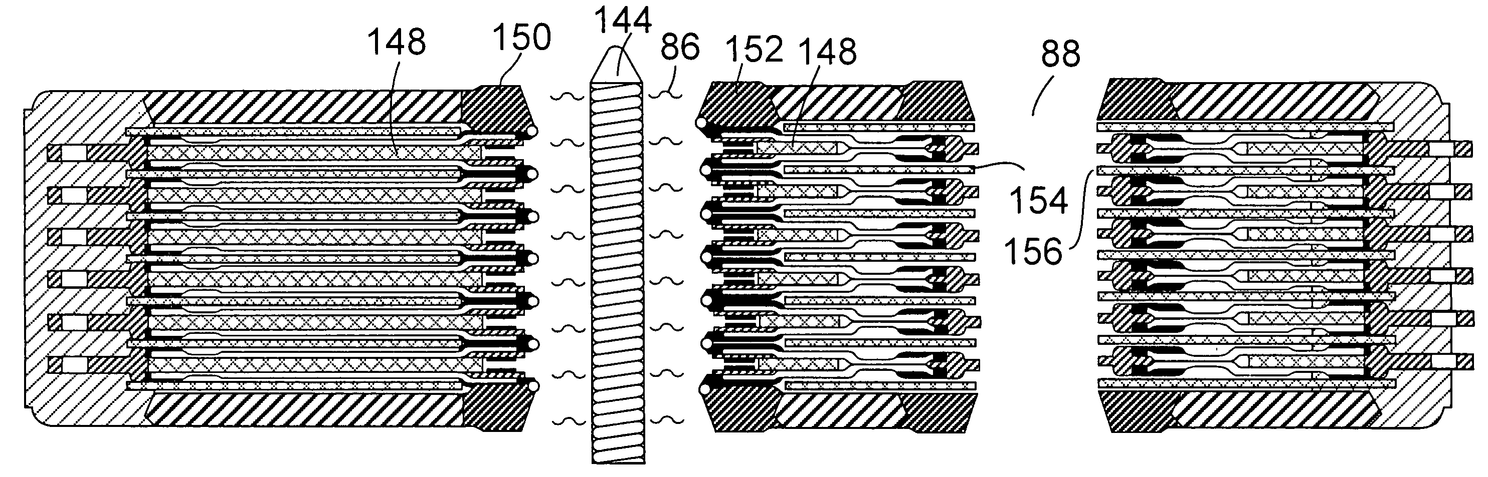
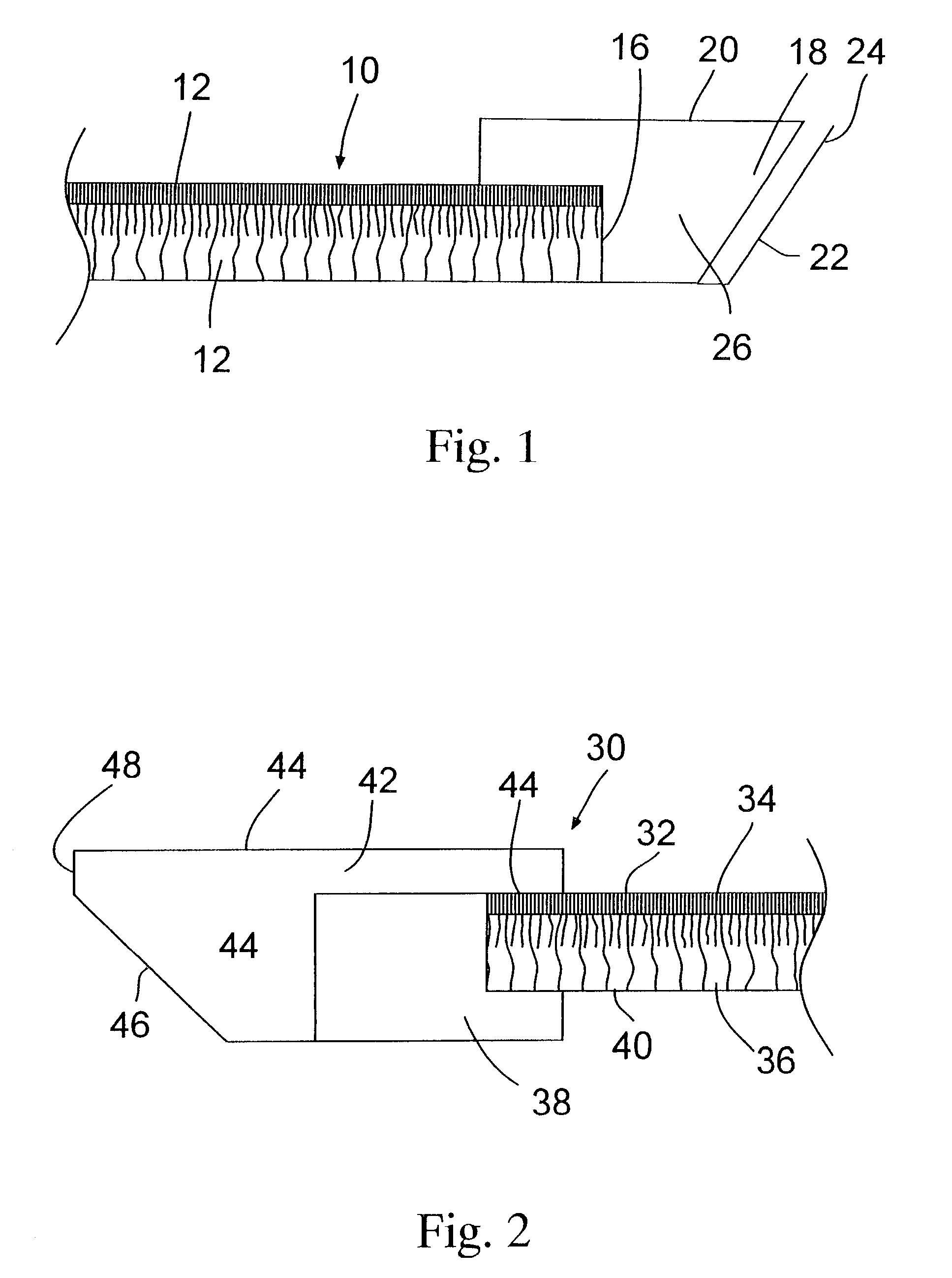
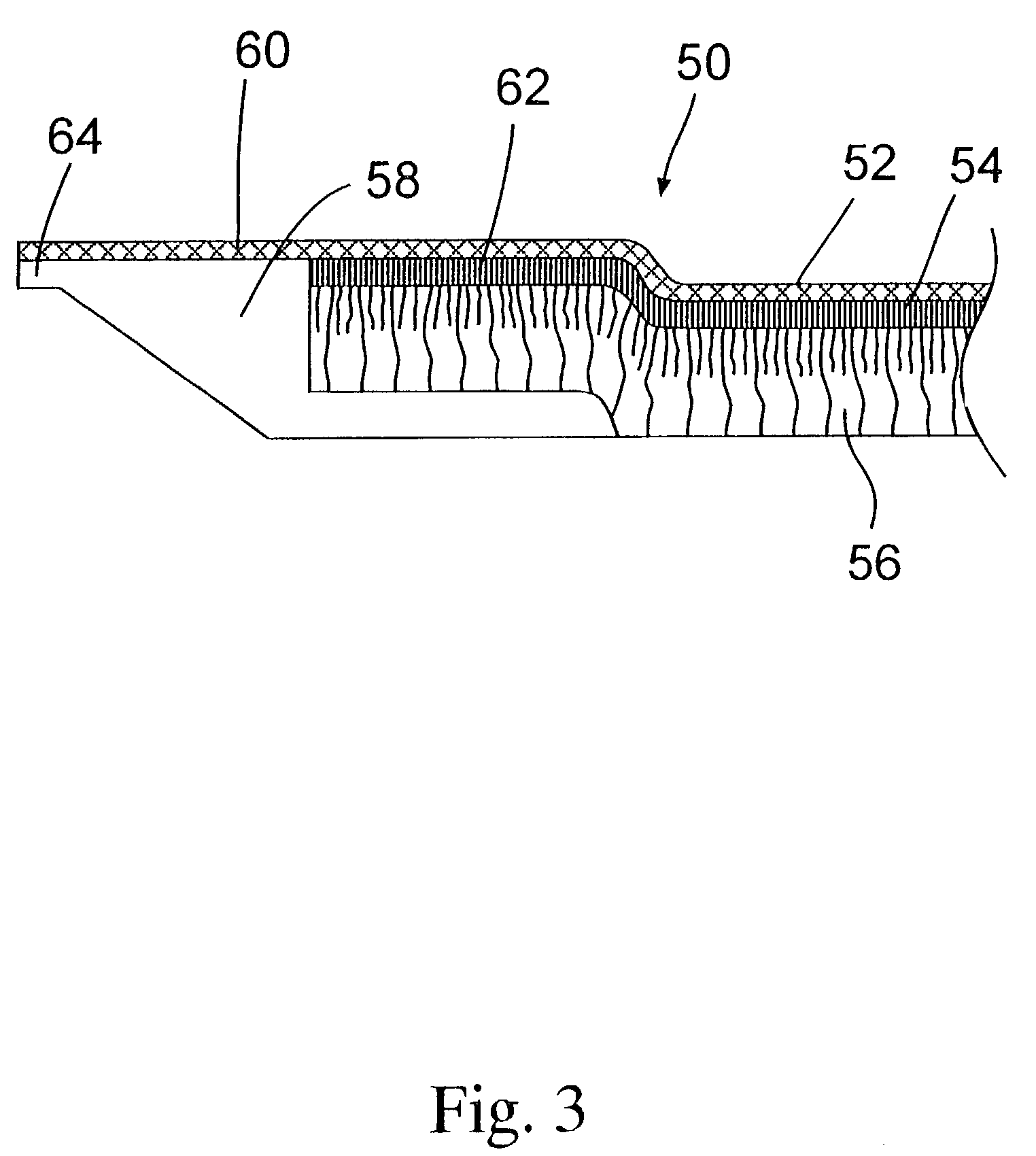
[0024]The present invention utilizes filtration membrane elements that can be selectively sealed in a stacked configuration to effect separation of filtrate from feed or feed and retentate. The filtration membrane element comprises a membrane layer having one edge thereof bonded to a thermoplastic polymeric composition. Preferably, the bonded thermoplastic polymeric composition has a top surface and a bottom surface configured so that they converge toward each other and form an end or tip area. The end or tip area is configured so that it absorbs radiant heat energy or a non heat energy such as ultrasonic energy which is absorbed by the end and converted to heat energy. When exposed to such energy, the end or tip preferentially melts prior to the main body of the thermoplastic polymeric composition. This feature permits control of the direction that the molten thermoplastic polymeric composition flows that, in turn, permits controlling selective areas of a filtration apparatus to be...


PUM

PropertyMeasurementUnit
permeableaaaaaaaaaa
permeateaaaaaaaaaa
chemical compatibilityaaaaaaaaaa

Abstract

A process for making a fluid processing module is provided wherein a plurality of filtration elements is alternated with a fluid porous layer to form a stack. The filtration elements comprise a membrane sheet having a thermoplastic element bonded to a portion of an edge of the membrane. An opening is provided either through the membrane or through the thermoplastic element. A portion of the thermoplastic element extends into the opening and can be sealed to an adjacent positioned thermoplastic element to seal the porous sheet positioned between adjacently positioned membranes from fluid communication with the opening. Sealing can be effected by extending a heating element through the opening of the stack to effect simultaneous sealing of a plurality of thermoplastic elements.

Description

BACKGROUND OF THE INVENTION[0001]This invention relates to a process for making a fluid processing module such as a membrane filtration apparatus for effecting filtration of a liquid composition wherein a feed liquid is introduced into the apparatus and a filtrate stream and, optionally a retentate stream are removed from the apparatus. More particularly, this invention relates to a process for making a fluid processing module such as membrane filtration apparatus that are formed by indirect heat sealing of a polymeric composition.[0002]For convenience, this invention will be described in detail with reference to a filtration module. However, it is to be understood that the process of this invention is equally applicable for making other fluid processing modules such as manifolds, heat exchangers, dialysers, desalters, degassers and the like. Prior to the present invention, liquids have been filtered within a plurality of filter modules that are stacked between manifolds or individu...

Claims


Application Information

Patent Timeline
Patent Type & Authority Patents(United States)
IPC IPC(8): B29C65/18B01D63/00B01D63/08B01D65/00B29C65/00B29C65/02B29C65/08B29C65/14F28D9/00F28F21/06
CPCB01D63/081B29C66/727B01D63/084B01D65/003B29C65/02B29C65/1451B29C66/137B29C66/21B29C66/304B29C66/45B29C66/612B29C66/80F28D9/00F28F21/065B01D63/082B29C66/30341B29C66/843B29C65/00B29C65/08B29K2101/12B29L2009/001B29L2031/14Y10S264/48B29C66/7392B29C66/73921
Inventor VIGNA, JAMES J.KELLY, JR., JAMES E.MERRILL, WAYNE S.
Owner MILLIPORE CORP
Why Eureka
Try Eureka