
Power control device for construction machine

a technology for controlling devices and construction machines, applied in the direction of electric generator control, electric control, instruments, etc., can solve the problems of inability to drive the compressor, the interior of the cab may not be comfortable, and the cooling capacity of the air conditioner is eventually lost, so as to avoid prevent the exhaustion of the battery. , the effect of avoiding the exhaustion of the battery

Inactive Publication Date: 2006-08-29
KOBELCO CONSTR MASCH CO LTD
View PDF12 Cites 14 Cited by
  • Summary
  • Abstract
  • Description
  • Claims
  • Application Information

AI Technical Summary

Benefits of technology

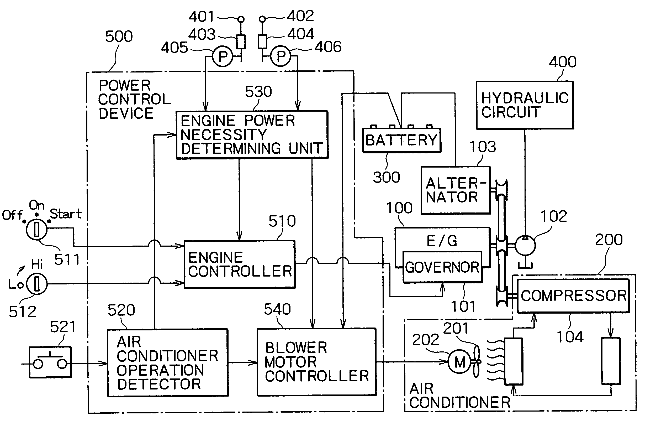
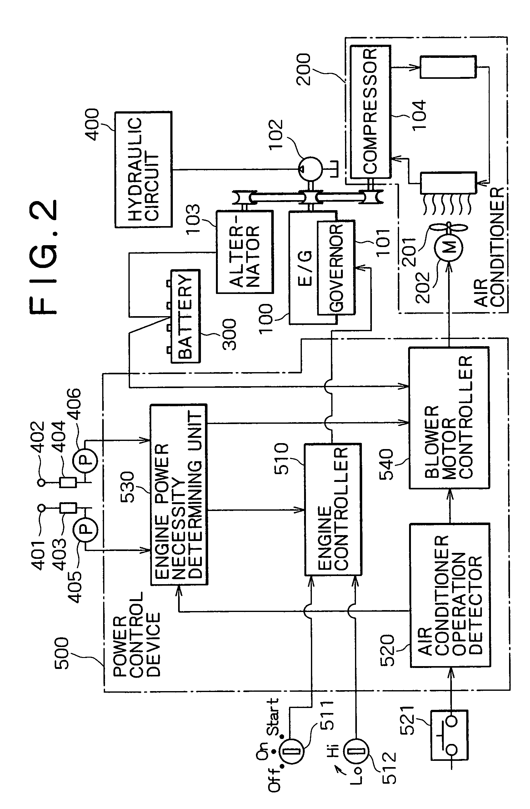
The present invention provides a power control device for a construction machine that can appropriately perform air conditioning of the interior of a cab even when the engine is not in use. The device includes an engine stop means for stopping the engine automatically when it is not necessary to drive the actuator, an air conditioner for conditioning the air in the interior of the cab, and an air conditioner operation maintaining means for maintaining at least a state of minimum operation of the air conditioner when the engine power necessity determining means determines that power is not necessary. This ensures that the interior of the cab is kept comfortable even when the operator returns after a while, leading to improvement of working efficiency. Additionally, the device may have a battery and battery supply electric power detecting means for detecting a residual quantity of electric power supplied by the battery, and the air conditioner may have a blower fan driven with the electric power supplied from the battery. This ensures that the interior of the cab is kept comfortable while avoiding exhaustion of the battery.

Problems solved by technology

However, in the construction machine having such an auto-stop function and with an air conditioner installed within a cab, since a compressor of the air conditioner is directly connected to the engine, the compressor becomes unable to be driven upon automatic stop of the engine and a cooling capacity of the air conditioner is eventually lost.
Therefore, for example in the summer season, when the operator leaves the construction machine without turn-off of an ignition key and returns after a while, an interior of the cab may be no longer comfortable because of a rise in internal temperature, thus making it impossible for the operator to enter the cab and resume operation, with consequent deterioration of a working efficiency.

Method used


Image

  • Power control device for construction machine
  • Power control device for construction machine
  • Power control device for construction machine

Examples


first embodiment

(a) FIRST EMBODIMENT

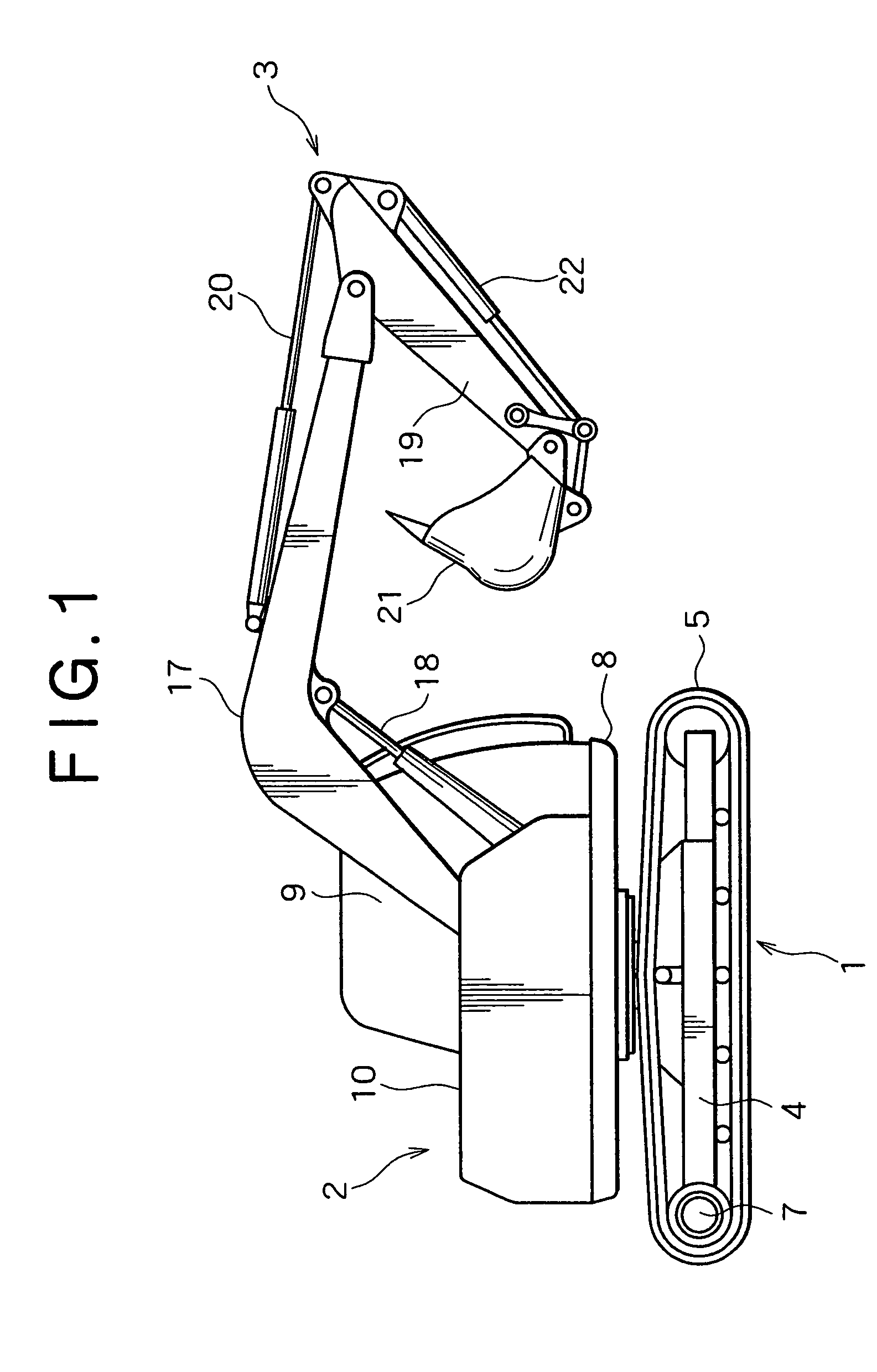
[0022]FIG. 1 is a diagram showing an entire configuration of a crawler type hydraulic excavator. As shown in the figure, a body of the hydraulic excavator as an example of a construction machine is made up of a lower traveling body 1 and an upper rotating body 2. An attachment 3 for excavation is attached to a front portion of the upper rotating body 2 so as to be raised and lowered freely.

[0023]The lower traveling body 1 comprises right and left crawler frames 4 and right and left crawlers 5, which are shown on only one side. The crawlers 5 are rotated independently by right and left traveling motors 7, causing the machine to travel. The upper rotating body 2 comprises a rotating frame 8, a cab 9 and a machine room 10. The cab 9 has a substantially hermetically sealed structure which is shut off from the outside air for protecting an operator from exterior noises, dust, etc. An air conditioner (not shown) is provided for ensuring comfortableness in the cab. The ...

second embodiment

(b) SECOND EMBODIMENT

[0040]FIG. 4 is a functional block diagram of a power control device of a crawler type hydraulic excavator according to a second embodiment of the present invention.

Elements common to the first embodiment are identified by the same reference numerals as in the first embodiment and tautological explanations thereof will be omitted.

[0041]In FIG. 4, reference numeral 600 denotes an auxiliary engine (an example of the auxiliary power source). Power generated by the auxiliary engine, which is smaller than the power generated by the engine 100, is such a degree of power for permitting operation of the compressor 104 and blower motor 202 in the air conditioner 200. The output of the auxiliary engine 600 is controlled by a dedicated governor 601 and a generator (alternator) 602 is directly connected to an output shaft of the auxiliary engine 600. Further, the compressor 104 is connected to the output shaft of the auxiliary engine 600 (not the engine 100) through a timin...

third embodiment

(c) THIRD EMBODIMENT

[0049]FIG. 6 is a functional block diagram of a power control device for a crawler type hydraulic excavator according to a third embodiment of the present invention. In this third embodiment, elements common to the first embodiment are identified by the same reference numerals as in the first embodiment and tautological explanations thereof will be omitted.

[0050]As shown in FIG. 6, a power control device 500b according to the third embodiment of the present invention is provided with a delay timer (corresponding to the air conditioner operation maintaining means) 560. The delay timer 560 is configured so that in accordance with a command provided from the engine controller 510 the blower motor controller 540 stops the operation of the blower fan 201 upon lapse of a predetermined time after stop of the engine 100.

[0051]FIG. 7 is a flow chart showing an example of operation of this device. A description will be given with reference to the same figure. In the power ...


PUM


Abstract

A power control device for a construction machine of the present invention is characterized by including an engine, an actuator adapted to be driven with power of the engine, an engine controller for stopping the engine automatically when it is not necessary to drive the actuator, and an air conditioner for conditioning the air in an interior of a cab of the construction machine, and in which when an air conditioner operation detecting unit detects that the air conditioner is in operation and even when an engine power necessity determining unit determines that the power of the engine is not necessary, automatic stop of the engine by the engine controller is prevented.

Description

TECHNICAL FIELD[0001]The present invention relates to a power control device for a construction machine such as a hydraulic excavator or a crane.BACKGROUND ART[0002]In Japanese Patent Laid-Open Nos. 2000-96627 and 2001-41069, there is disclosed a construction machine having an auto-stop function for stopping an engine automatically upon establishment of preset auto-stop conditions (e.g., a state in which a gate lever for opening and closing a gateway for operator is opened and a lever for operating a working actuator is not operated).[0003]However, in the construction machine having such an auto-stop function and with an air conditioner installed within a cab, since a compressor of the air conditioner is directly connected to the engine, the compressor becomes unable to be driven upon automatic stop of the engine and a cooling capacity of the air conditioner is eventually lost. Therefore, for example in the summer season, when the operator leaves the construction machine without tur...

Claims


Application Information

Patent Timeline
Patent Type & Authority Patents(United States)
IPC IPC(8): F02N11/06G06F7/00B60H1/32E02F9/20B60H1/00B66C13/22B66C13/52E02F9/16E02F9/22E02F9/24F02D29/00F02D29/02F02D29/04F02D41/04
CPCB60H1/00378B60H1/322F02N11/084E02F9/24E02F9/2246F02D41/042Y02T10/40
Inventor ASAKAGE, TOMOHIKOKINUGAWA, HIDEKI
Owner KOBELCO CONSTR MASCH CO LTD
Learn More