
Apparatus and method for the heat treatment of lignocellulosic material

a technology of lignocellulosic material and apparatus, which is applied in the direction of lighting and heating apparatus, furnace types, drying, etc., can solve the problems of material treatment splitting or breaking, difficult or even impossible to carry out material treatment inside, and difficult to achieve in practice, etc., to achieve simple and effective high temperature treatment, preserve the mechanical properties of the material, and easy to carry out in practice

Inactive Publication Date: 2006-09-05
PCI INDS
View PDF17 Cites 5 Cited by
  • Summary
  • Abstract
  • Description
  • Claims
  • Application Information

AI Technical Summary

Benefits of technology

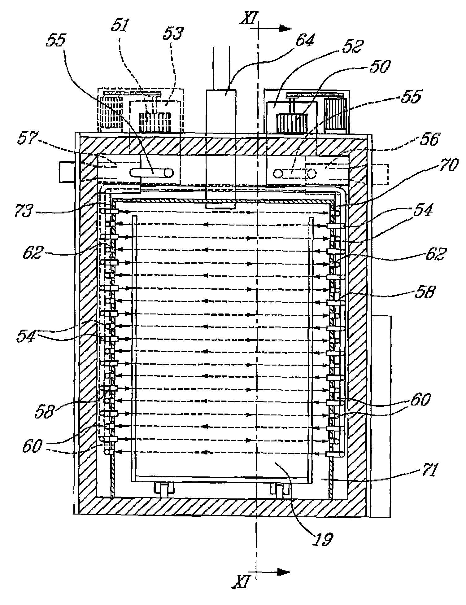
[0005]The invention discloses a method and apparatus making it possible to overcome these disadvantages. It provides simple, effective, high temperature treatment, preserving the mechanical properties of the material, and is easy to carry out in practice. The apparatus of the invention has a simple and robust structure, and makes it possible to provide effective treatment without the need for complicated adjustments. In particular, the flow of gases within the treatment chamber is substantially uniform and contributes to a more homogenous temperature within the material being treated and a more efficient drying of the material.

Problems solved by technology

The closed-circuit heating step disclosed in this document does not make it possible to ensure residual humidity, remaining after the drying step, is completely eliminated.
Additionally, the use of the gases released by the material as a fuel involves control of the treatment plant which is difficult to achieve in practice.
Finally, injecting water for cooling leads to the material treated splitting or breaking up.
The cell disclosed in that document for carrying out the method has corresponding disadvantages, and in practice, it is difficult or even impossible to carry out material treatment inside it.
In particular, it is difficult, with this apparatus, to ensure that the gases released are subject to combustion, as proposed in the method, and it is also difficult and dangerous to carry out heating in a closed circuit.
However, the arrangement of this apparatus, which is further described below, creates a unidirectional flow of gas within the treatment chamber that results in temperature inhomogeneity within the material being treated.

Method used


Image

  • Apparatus and method for the heat treatment of lignocellulosic material
  • Apparatus and method for the heat treatment of lignocellulosic material
  • Apparatus and method for the heat treatment of lignocellulosic material

Examples


Embodiment Construction

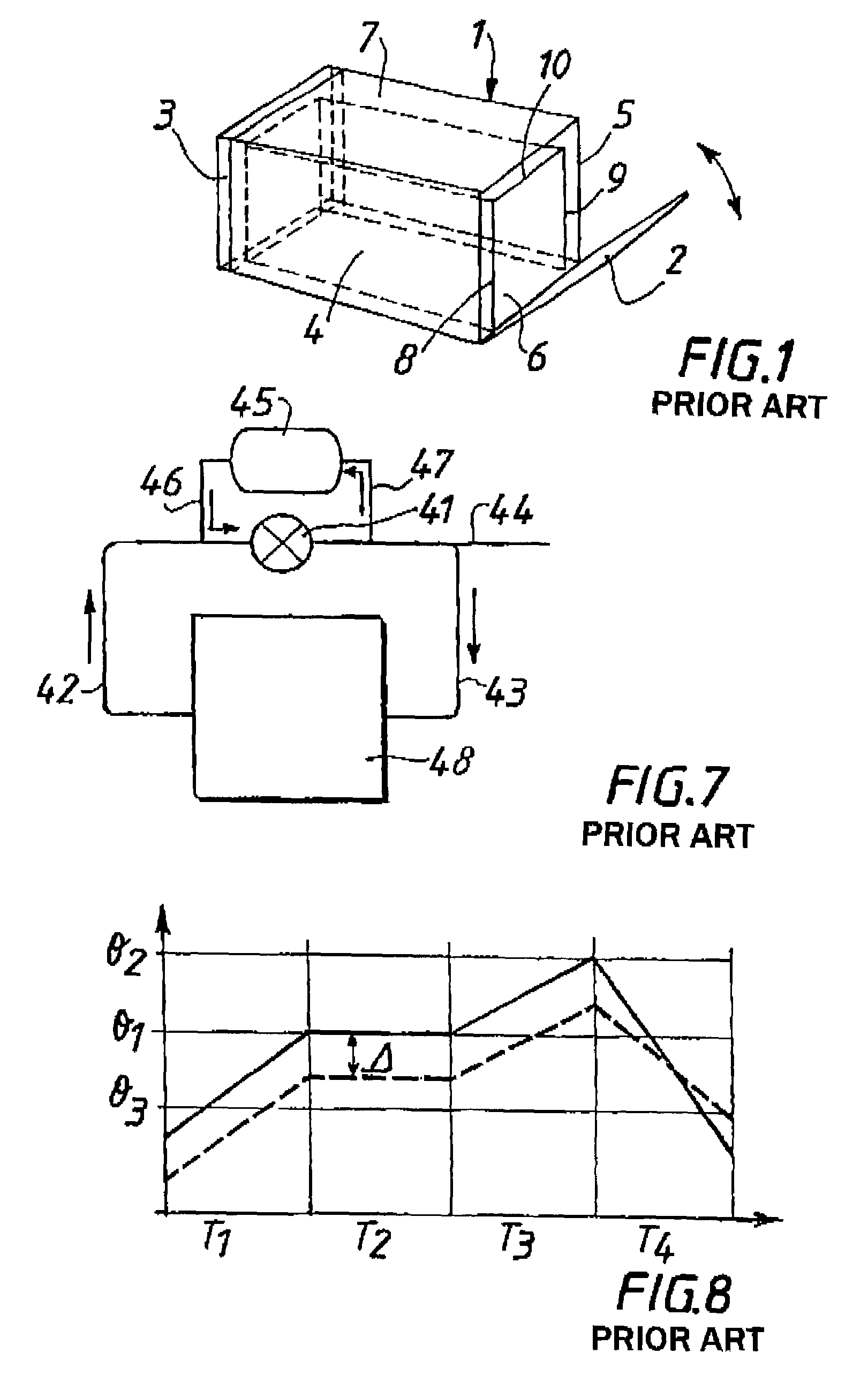
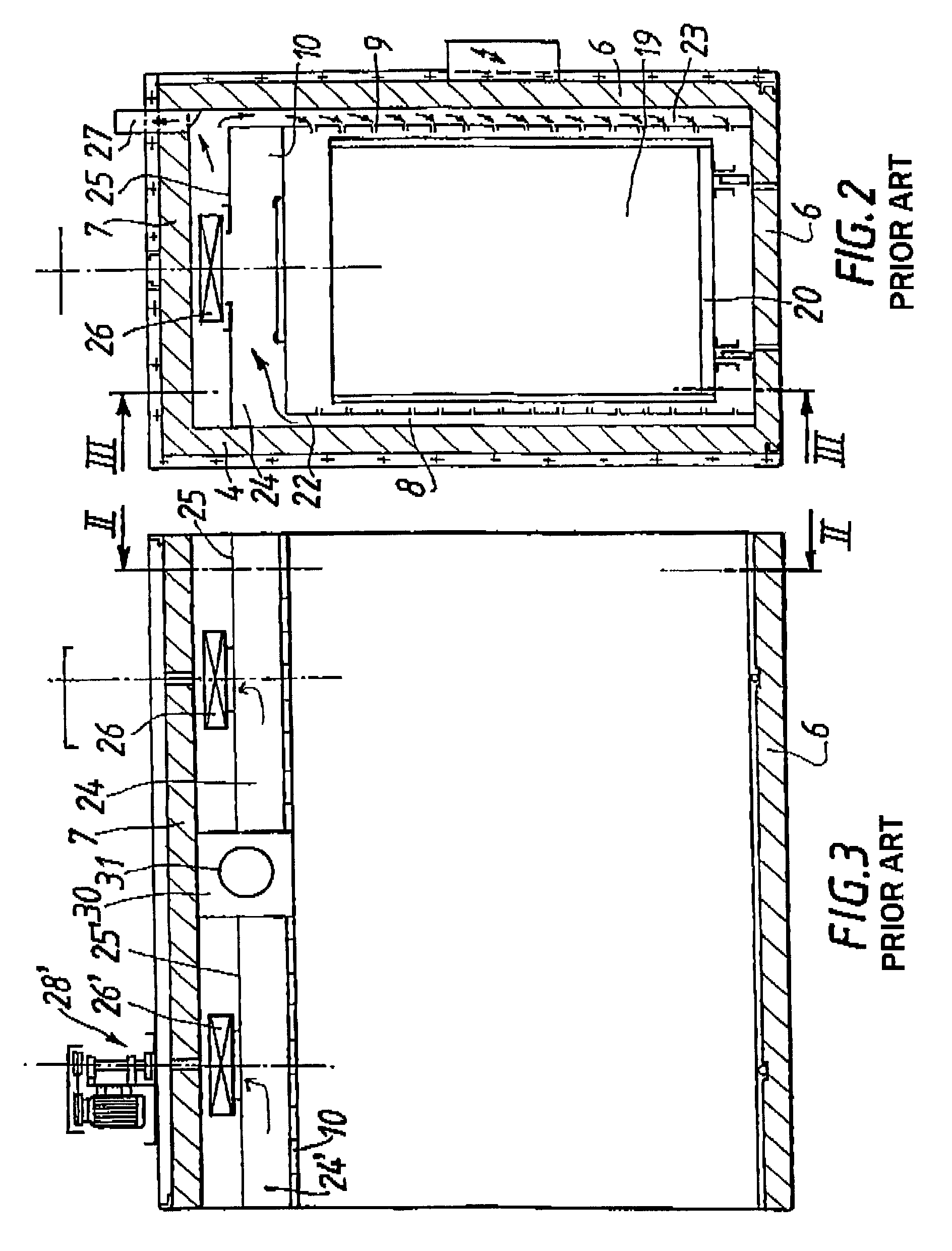
[0028]For explanatory purposes, FIG. 1 through 8 will be generally discussed prior to the detailed description of the invention.

[0029]FIG. 1 is a diagrammatical view in perspective of an apparatus for high temperature treatment of lignocellulosic material. The treatment apparatus comprises a cell 1, forming a rectangular cross-section tunnel designed to receive the material to be treated. The ends of cell 1 can be closed by means of a door 2 and a base 3. This configuration makes it possible, if needs be, to assemble several cells, for example for treating long or bulky charges. A cell according to the invention can, for example, measure 4.5 meters long, 1.45 meters wide and 2.15 meters high. These dimensions provide a useful treatment volume of some 6 to 10 cubic meters of lignocellulosic material.

[0030]Each cell comprises an outer sealed wall, preferably heat-insulated, ensuring mechanical stability of the cell, a treatment chamber with two lateral panels 4, 5, a floor 6 and a cei...


PUM


Abstract

There is provided an apparatus and a method for heat treatment of lignocellulosic material. The apparatus comprises a treatment chamber and devices for circulating and recovering gases from the treatment chamber such as to provide a uniform temperature within the chamber and allow efficient drying of the material. This is achieved by injecting and recovering the gases from at least two sides of the treatment chamber.

Description

CROSS-REFERENCE TO RELATED APPLICATIONS[0001]This is the first application filed for the present invention.TECHNICAL FIELD[0002]The present invention relates to apparatus and to a method for carrying out high temperature treatment of lignocellulosic material, such as wood.BACKGROUND OF THE INVENTION[0003]High temperature treatment of lignocellulosic material, such as wood, makes it possible to reduce their moisture content and improve their stability characteristics.[0004]Various methods and apparatus for carrying out high temperature treatment of lignocellulosic materials are known. FR-A-2,720,969 discloses such a method and a cell for carrying it out. This document discloses drying of the materials, followed by heating in a closed circuit during which the gases released by the material are employed as a fuel, and finally, cooling by injection of water. The closed-circuit heating step disclosed in this document does not make it possible to ensure residual humidity, remaining after ...

Claims


Application Information

Patent Timeline
Patent Type & Authority Patents(United States)
IPC IPC(8): F26B25/06F26B3/02F26B9/06F26B21/00F26B21/02F26B21/10F26B23/02
CPCF26B9/06F26B21/004F26B21/02F26B23/02F26B25/06F26B21/10F26B2210/16
Inventor BERNON, JEAN-PIERREROBERT, BERNARDROBERT, FABRICEDREVET, JACKY
Owner PCI INDS
Learn More