

Thermoelectric generating device
a technology of generating device and thermoelectric power, which is applied in the direction of thermoelectric devices, mechanical equipment, machines/engines, etc., to achieve the effect of generating maximum electricity
- Summary
- Abstract
- Description
- Claims
- Application Information
AI Technical Summary
Benefits of technology
Problems solved by technology
Method used
Image

Examples
first embodiment
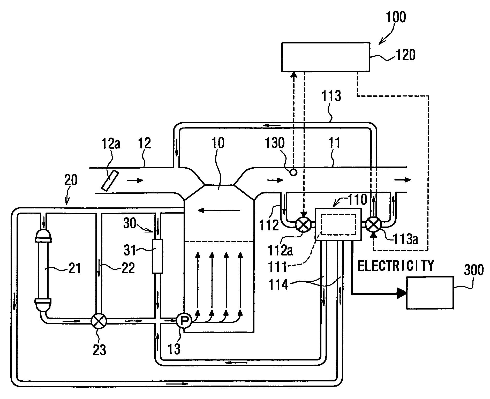
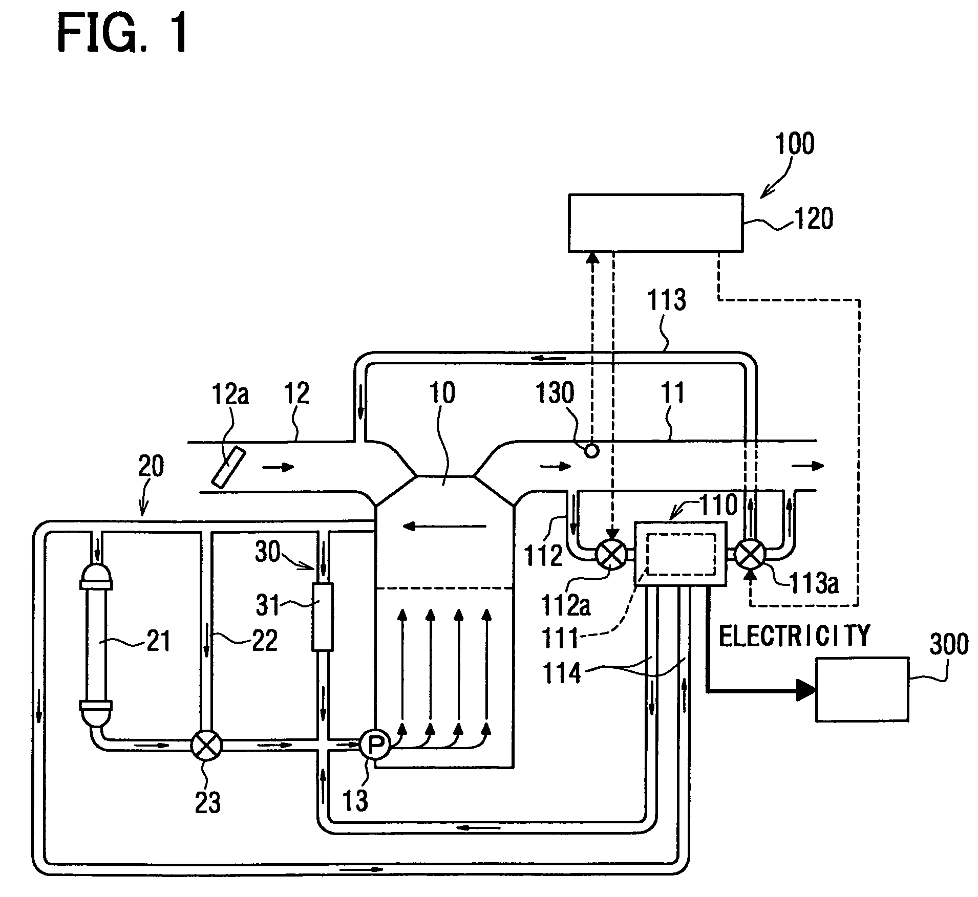
[0029]A thermoelectric generating device 100 of the present invention is used for an automobile having a water-cooled engine 10. A thermoelectric element 111 of the device 100 has a function of generating an electricity and a function of cooling an exhaust gas for re-circulation, which is referred to as EGR.
[0030]Referring to FIG. 1, an engine 10 is provided with an intake pipe 12 for introducing an air for combustion and an exhaust pipe 11 for introducing the exhaust gas. A throttle valve 12a is disposed in the intake pipe 12 which varies an opening degree to adjust an amount of intake air.
[0031]The engine 10 is provided with an engine-coolant circuit 20. An engine coolant is circulated in the engine-coolant circuit 20 through a radiator 21 by a water-pump 13. The water pump 13 is driven by the engine 10. The coolant is cooled by the radiator 21 and the temperature of the engine 10 is kept in a proper range. The engine-coolant circuit 20 is provided with a bypass passage 22 and a t...
second embodiment
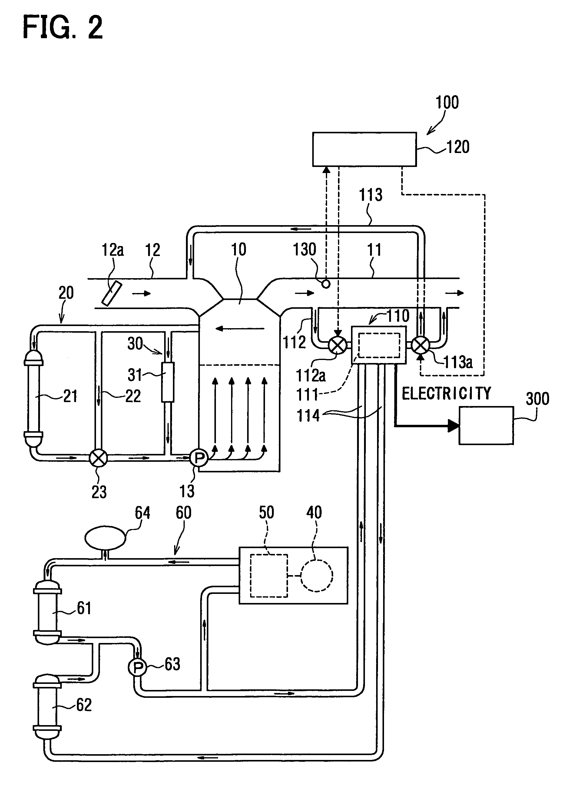
[0054]FIG. 2 shows a second embodiment. In the second embodiment, the thermoelectric generating device is applied to a hybrid vehicle which includes the engine 10 and a driving motor 40 for driving the hybrid vehicle.
[0055]The driving motor 40 is driven with receiving the electricity from the battery and is controlled the rotational speed thereof by an inverter 50. The engine 10 and the driving motor 40 are selectively driven according to the driving condition of the vehicle. The inverter 50, the driving motor 40, and the battery (not shown) are provided with an inverter coolant circuit 60 for cooling components which are under the operation.
[0056]The inverter coolant circuit 60 is provided with a radiator 61 and a coolant in the circuit 60 is circulated by an electric pump 63. The coolant pipe 114 is connected with the inverter coolant circuit 60 at positions upstream and downstream from the electric pump 63. A second radiator 62 which radiates the heat absorbed from the exhaust ga...
third embodiment
[0063]In the third embodiment, the same parts and components as those in the first embodiment are indicated with the same reference numerals and same description will not be reiterated.
[0064]Referring to FIG. 3, the engine 10 is controlled by an engine controller 14. The engine controller 14 receives signals such as an engine speed signal, a throttle opening degree signal, a vehicle velocity signal and the like. The engine controller 14 has a map in which an amount of fuel injection is memorized. The amount of fuel injection is based on the engine speed signal and the throttle opening degree signal. The fuel is injected into the intake pipe 12 according to the map. The engine controller 14 sends signals to and receives signals from the controller 120.
[0065]The coolant pipe 114 diverges from the engine-coolant circuit 20 at downstream from the radiator 21 and converges on the engine-coolant circuit 20 at upstream from the water-pump 13 through the thermoelectric generator 110. The co...
PUM
 Abstract
Description
Claims
Application Information