Oneway clutch assembly

a one-way clutch and assembly technology, applied in the direction of clutches, mechanical actuated clutches, freewheel clutches, etc., can solve the disadvantageous increase in the width dimension in the axial direction thereof by the projected portion of the flange, and achieve the effect of increasing the frictional torque and reducing the width dimension

Inactive Publication Date: 2006-09-05
NSK WARNER
View PDF13 Cites 6 Cited by
  • Summary
  • Abstract
  • Description
  • Claims
  • Application Information

AI Technical Summary

Benefits of technology

[0013]The present invention has been contrived taking circumstances as described above into consideration, and an object thereof is to provide a oneway clutch assembly which is capable of reducing the width dimension in the axial direction thereof to the minimum and, at the same time, of further increasing a frictional torque between the main body unit of the oneway clutch and the outer race, or the like, at the time of idling rotation of the outer race or the like.
[0019]According to the present invention, an engagement projection extending in the axial direction is provided on an annular side plate, and this engagement projection is fitted in between an opening of a frictional engagement ring (C-shaped retaining ring). As a result, it is rendered possible to reduce the width dimension in the axial direction thereof to the minimum, and at the same time, to further increase a frictional torque between the main body unit of the oneway clutch and the outer race, or the like, at the time of idling rotation of the outer race or the like.

Problems solved by technology

However, the annular side plate has a flange which is projected in the axial direction on the outer peripheral end thereof and the above-described window portion is provided on this flange, so that the width dimension in the axial direction thereof is disadvantageously increased by the projected portion of the flange.

Method used


Image

  • Oneway clutch assembly
  • Oneway clutch assembly
  • Oneway clutch assembly

Examples


first embodiment

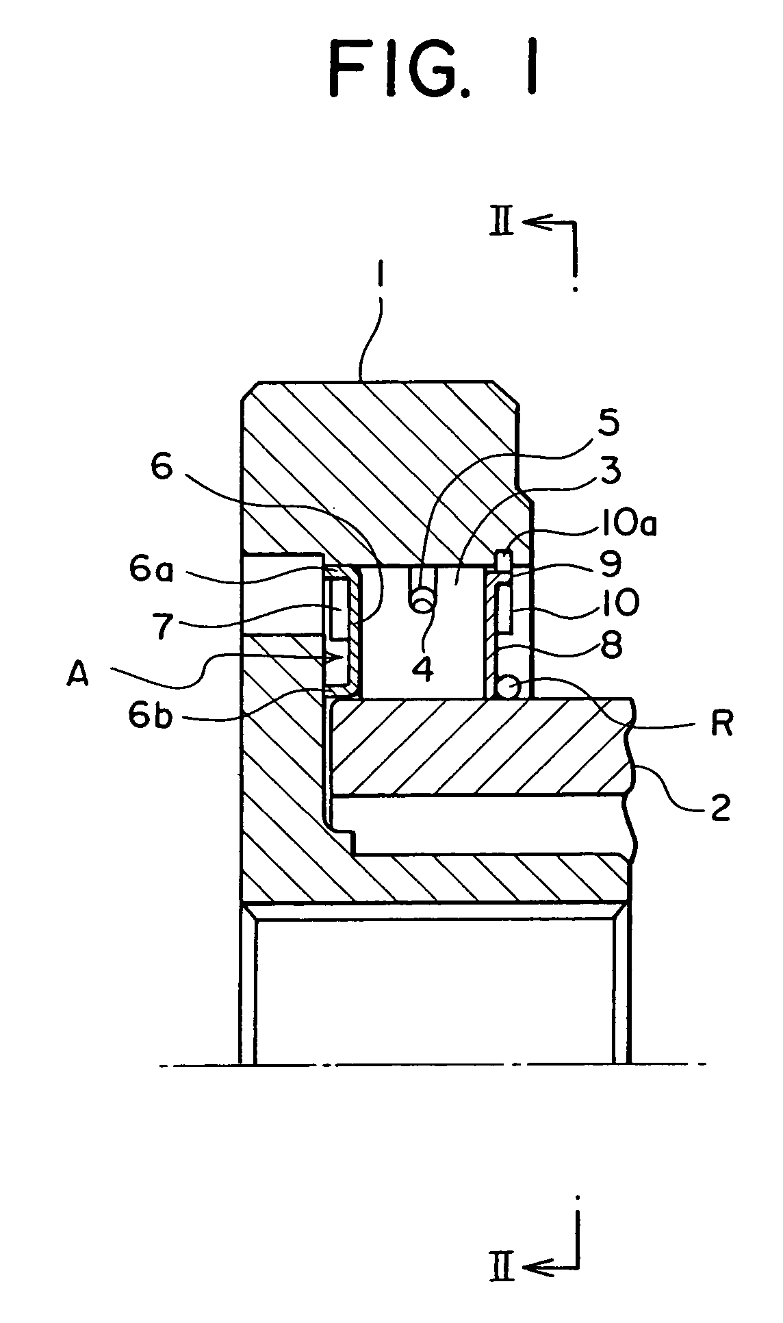
[0026]FIG. 1 is a cross-sectional view of a one-way clutch assembly according to the first embodiment of the present invention.

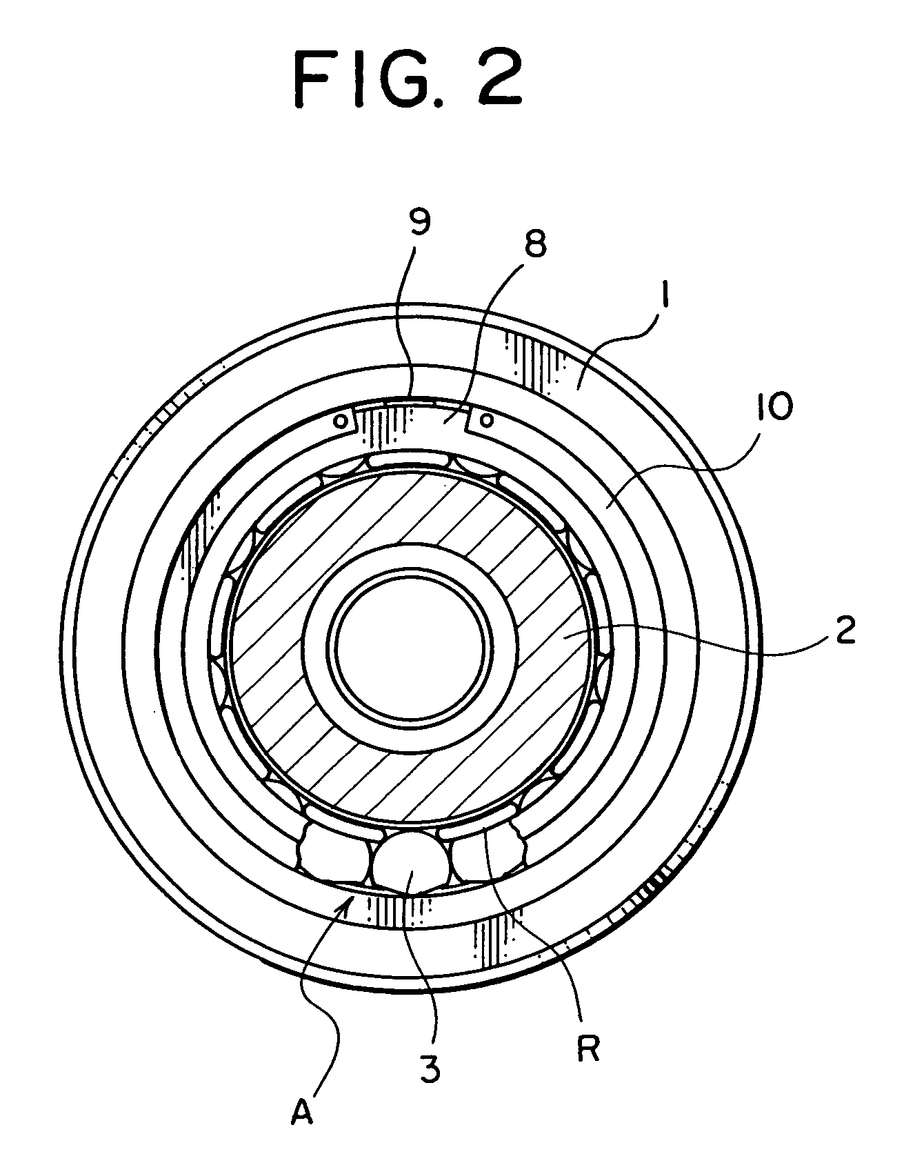
[0027]FIG. 2 is a cross-sectional view taken along the line II—II in FIG. 1.

[0028]FIG. 3A is a side view of a small side plate and FIG. 3B is a cross-sectional view of the small side plate.

[0029]In the oneway clutch assembly according to the present embodiment, sprags serving as torque transmitting members 3 are disposed between an outer race 1 and an inner race 2, and a groove 4 is formed on the outer periphery of each torque transmitting member 3 (sprag) around which a garter spring 5 is wound.

[0030]This garter spring 5 imparts a biasing force for inclining each torque transmitting member 3 (sprag) in an engageable direction. Note that the torque transmitting members 3 (sprags) are retained at regular intervals in the circumferential direction by a wire retainer R (wire cage).

[0031]A side plate 6 having a U-shaped cross section (hereinafter called the “U-s...

second embodiment

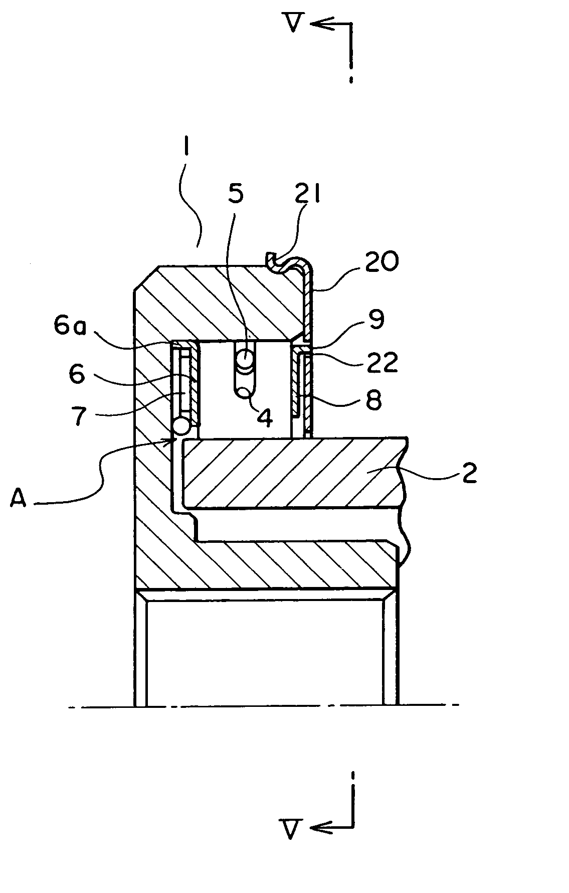
[0038]FIG. 4 is a cross-sectional view of a one-way clutch assembly according to the second embodiment of the present invention.

[0039]FIG. 5 is a cross-sectional view taken along the line V—V in FIG. 4.

[0040]The second embodiment has the same basic structure as that of the first embodiment described above, so that description thereof will be omitted.

[0041]In the second embodiment, there is provided a side plate 20 (hereinafter called the large side plate) which is elastically engaged with the outer periphery of the outer race 1, instead of the frictional engagement ring-shaped member 10 (C-shaped retaining ring), so as to restrict an axial movement of the main body unit A of the oneway clutch.

[0042]As shown in FIG. 4 and FIG. 5, a plurality of engagement pieces 21 which are bent in the axial direction and in the radial direction to be elastically engaged with the other periphery of the outer race 1 are formed on the outer periphery of the large side plate 20.

[0043]The large side pla...


PUM


Abstract

A oneway clutch assembly comprises an outer race and an inner race, torque transmitting members disposed between the outer race and the inner race, a biasing spring for biasing the torque transmitting members, side plates disposed on the both sides of the torque transmitting members in the axial direction thereof, and detachment preventing means for restricting movements of the torque transmitting members, the biasing spring, and the side plates in the axial direction, and being elastically engaged with the outer race or the inner race. One of the side plates is provided with an engagement projection extended in the axial direction and the engagement projection is fitted in the detachment preventing means.

Description

[0001]This application claims the benefit of Japanese Patent application No. 2003-338459 which is hereby incorporated by reference.BACKGROUND OF THE INVENTION[0002]1. Field of the Invention[0003]The present invention relates to a one-way clutch assembly which is used, for example, in a starter of a motorcycle or the like.[0004]2. Related Background Art[0005]In the oneway clutch assembly, the constituent members thereof except an outer race, an inner race and a C-shaped retaining ring (hereinafter called the main body unit of the oneway clutch) are rotated slowly between the outer and inner races depending on increase, decrease, or the like, of vibrations or the number of rotations of the engine. This rotation is required for preventing a local abrasion of the outer race or the inner race, and the speed of this rotation is adjusted by an elastic ring or the like provided on a side plate or the like. The technologies therefor are disclosed, for example, in Japanese Utility Model Appli...

Claims


Application Information

Patent Timeline
Patent Type & Authority Patents(United States)
IPC IPC(8): F16D41/07F16D41/06F16D41/067
CPCF16D41/067F16D41/07
Inventor TAKASU, YASUHIDE
Owner NSK WARNER
Why Eureka
Try Eureka