Eureka AIR delivers breakthrough ideas for toughest innovation challenges, trusted by R&D personnel around the world.

Method and apparatus for controlling a pumping unit

Inactive Publication Date: 2006-09-05
DAVIS REVOCHBLE TRUST U T A DATED 12 28 2000
View PDF15 Cites 5 Cited by
  • Summary
  • Abstract
  • Description
  • Claims
  • Application Information

AI Technical Summary

Benefits of technology

[0007]To achieve the foregoing and other objects, and in accordance with the purposes of the present invention, as embodied and broadly described herein, this invention provides a method for reducing the pumping duty cycle of a pump assembly associated with a pumping oil, natural gas, or water well. An engine is connected with a pump assembly through a pneumatically actuated clutch and a selected event is determined to actuate the clutch to connect the engine with the pump assembly. A pressurized gas is supplied on the occurrence of the selected event to actuate the clutch to connect the pump assembly with the engine to remove liquid from the gas well to maintain an inflow of hydrocarbons from the producing formation.

Problems solved by technology

But the check valves seal against and move relative to the tubing string so that there is substantial wear of the down hole components.
This wear is increased when a tubing string and associated cased well bore are not perfectly vertical, but have significant amounts of deviation from vertical, i.e., the casing is “crooked”.
Thus, continuous pumping unnecessarily aggravates wear in the surface and down hole pumping unit system components.
It will be appreciated that replacing down hole components as a result of wear is expensive and time consuming since the entire pump string must be removed and refurbished.
But in remote locations where engines are used, it is not desirable to turn the engines on and off because of reliability problems, reduced battery life under repeated start cycles, and the labor needed to periodically return to a pump site.

Method used


Image

  • Method and apparatus for controlling a pumping unit
  • Method and apparatus for controlling a pumping unit
  • Method and apparatus for controlling a pumping unit

Examples


Embodiment Construction

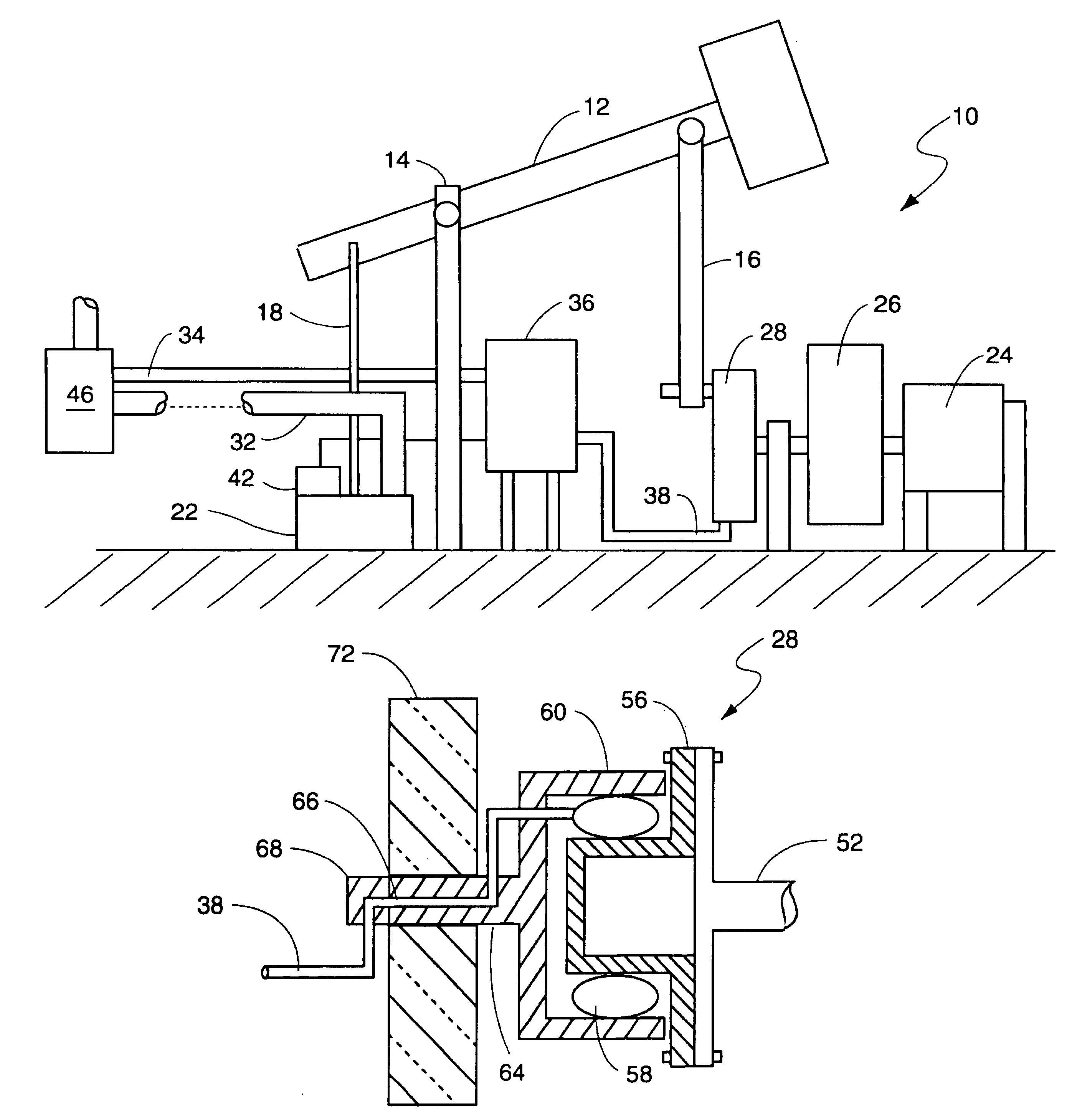
[0013]In accordance with the present invention, a gas actuated clutch is used to connect a natural gas powered engine to a pumping unit to cycle the pumping unit as needed to maintain a fluid level in a borehole between selected elevations and maintain a sustained inflow of hydrocarbons from the producing formation. The actuating gas is preferably natural gas from the well so that the actuating component is conveniently available at the well site.

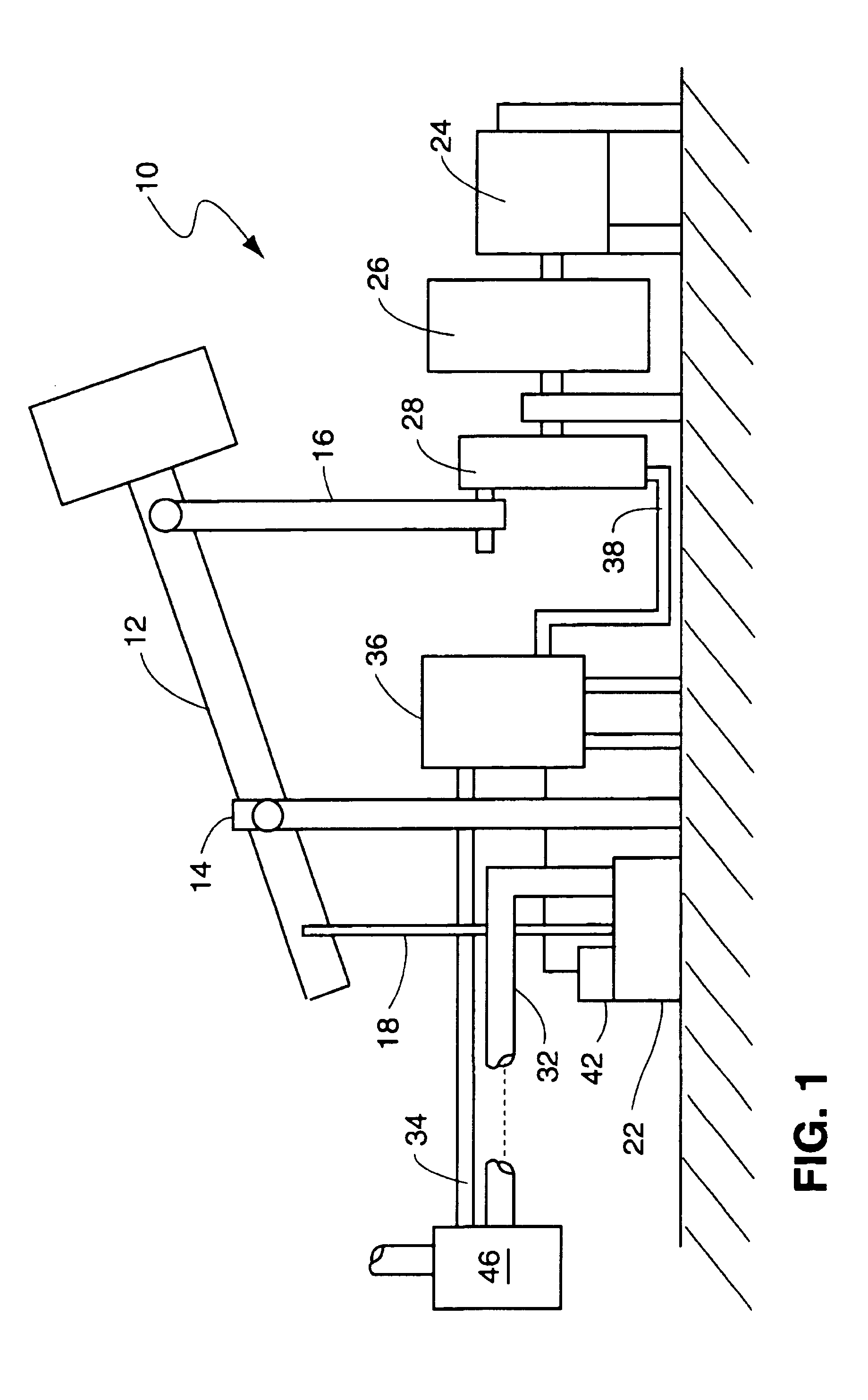
[0014]FIG. 1 is a pictorial illustration of one embodiment of the present invention. Pump unit 10 is comprised of a pump having lever arm 12, support pivot 14, crank arm 16 and sucker rods 18. Crank arm 16 operates as a conventional crank shaft and converts rotary motion from pneumatic clutch 28 to reciprocating motion for vertically pivoting lever arm 12 about support pivot 14 and vertically move attached sucker rods 18. Internal borehole pump configurations are well known and are not described herein.

[0015]Liquid, usually oil and water, i...


PUM


Abstract

Method and apparatus for reducing the pumping duty cycle of a pump assembly associated with an oil, natural gas, or water well with a concomitant reduction in the wear associated with the pump down hole components. An engine is connected with a pump assembly through a pneumatically actuated clutch and a selected event is determined to actuate the clutch to connect the engine with the pump assembly. The selected events may be a timed cycle determined from observations or a direct determination of liquid level in the well bore so that hydrocarbon production is maintained from the well bore. A pressurized gas is supplied on the occurrence of the selected event to actuate the clutch to connect the pump assembly with the engine to remove liquid from the gas well to maintain hydrocarbon production from the well.

Description

FIELD OF THE INVENTION[0001]This invention is directed to oil and gas field pumping units, and, more particularly, to control systems for minimizing the run time to reduce wear on the pumping unit and associated pump rods and tubing.BACKGROUND OF THE INVENTION[0002]Oil and gas field pumping units conventionally convert a rotary motion from an electric or gas powered engine to a vertical reciprocating motion for moving a subsurface pump and sucker rods in a tubing string for vertically removing liquid from an oil, gas, or water bearing formation. The subsurface pumps typically employ a series of lift check valves within a tubing string to cause vertical movement of liquid within the tubing string. But the check valves seal against and move relative to the tubing string so that there is substantial wear of the down hole components. This wear is increased when a tubing string and associated cased well bore are not perfectly vertical, but have significant amounts of deviation from verti...

Claims


Application Information

Patent Timeline
IPC IPC(8): F04B35/00E21B43/00F04B17/00F04B49/00
CPCE21B47/0007F04B49/02F04B47/02E21B47/008
Inventor DAVIS, JEFFREY
Owner DAVIS REVOCHBLE TRUST U T A DATED 12 28 2000
Why Eureka
Eureka Blog
Learn More