Splittable medical valve

a medical valve and split technology, applied in the field of medical devices, can solve the problems of not allowing replacement at a more distal location, and achieve the effect of convenient complete separation of the valve assembly and easy pulling apar

Inactive Publication Date: 2006-09-05
COOK MEDICAL TECH LLC
View PDF29 Cites 236 Cited by
  • Summary
  • Abstract
  • Description
  • Claims
  • Application Information

AI Technical Summary

Benefits of technology

[0009]The hemostatic valve includes at least one line of fissure through which the valve is opened to allow external access to the passageway. In one embodiment, the silicone valve body is formed with opposing scores or grooves formed nearly all the way through the inside or ou

Problems solved by technology

This provides a significant clinical benefit over existing splittable introducers that include an integral valve at

Method used


Image

  • Splittable medical valve
  • Splittable medical valve
  • Splittable medical valve

Examples


Embodiment Construction

[0047]A better understanding of the present invention will now be had upon reference to the following detailed description, when read in conjunction with the accompanying drawing, wherein like reference characters refer to like parts throughout the several views and different embodiments of the present invention.

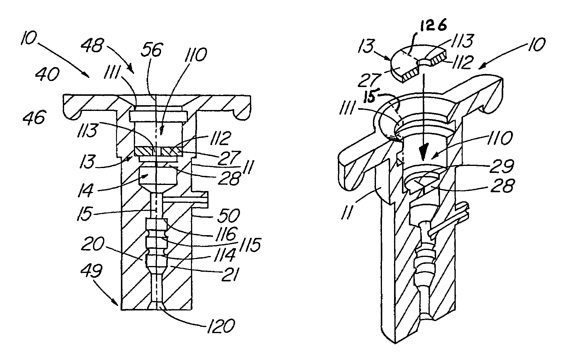
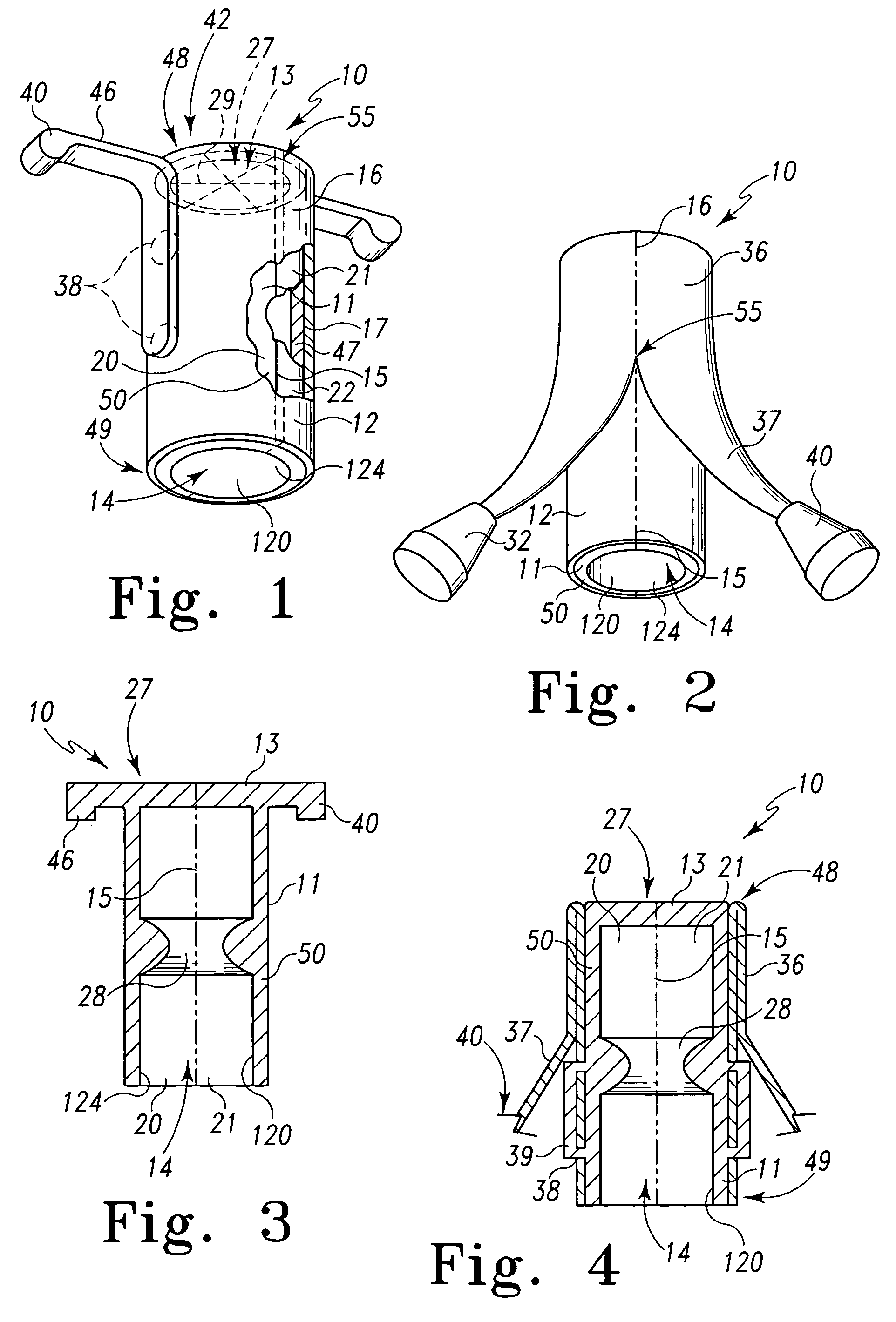
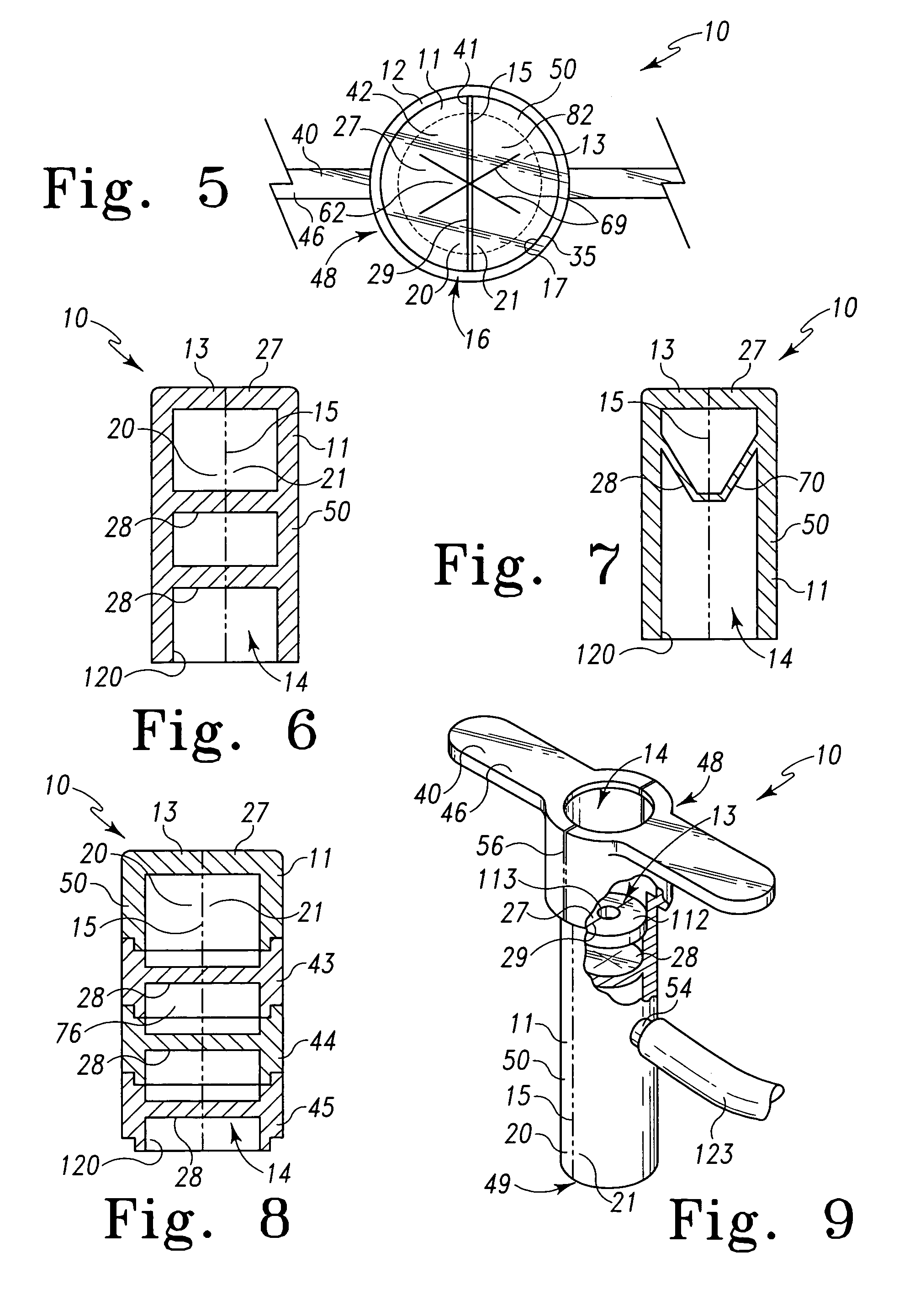
[0048]The splittable valve assembly 10 of the present invention, as embodied in FIGS. 1–35, comprises a hemostatic valve 11 that includes a valve body 50 with a passageway 14, at least one line of fissure 15 to permit the valve to split and allow external access along the length of the passageway, and at least one sealing element 13 configured to traverse the passageway 14, while permit the passage of an first medical device 57, such as a catheter, dilator, pacemaker lead, etc., while substantially preventing or eliminating the leakage or ‘flashback’ of blood or other bodily fluids. The splittable valve assembly 10 is designed for use with a second medical device, typically ...


PUM


Abstract

A hemostatic valve couples to a sheath proximal hub having an inside and an outside surface. The hemostatic valve has a valve body having a proximal porting and end, and a distal portion and end. A passageway extends longitudinally through the valve body between the proximal and distal ends. A sealing element is positioned within the passageway. The distal portion of the valve body includes a pair of contact surfaces forming an annular gap receiving the sheath proximal hub of the sheath so that the contact surfaces sandwich the sheath proximal hub forming a seal on both the inside and outside surfaces of the hub. The valve body and the sheath proximal hub includes two oppositely placed longitudinal lines of fissure that allow the hub to be separated into two halves with the valve body.

Description

CROSS-REFERENCE TO RELATED APPLICATIONS[0001]This application is based on provisional application Ser. No. 60 / 333,077 filed Nov. 6, 2001, and is a continuation-in-part of application Ser. No. 09 / 751,017 filed Dec. 28, 2000 now U.S. Pat. No. 6,712,791, which is in turn based on provisional application Ser. No. 60 / 173,758 filed Dec. 30, 1999.TECHNICAL FIELD[0002]This invention relates to medical devices, in particular to hemostatic valves for intravascular devices.BACKGROUND OF THE INVENTION[0003]Percutaneous placement of intravascular catheters, pacemaker leads, etc. involves blood loss that, while easily controllable especially during venous access, can become significant during long procedures. For example, procedures such as placement of leads in the coronary sinus for biventricular pacing, can last 4 hours, during which time the blood loss of up to 500–600 cc can represent a risk to the patient. Additionally, the open conduit into the body can become a source of infection to the ...

Claims


Application Information

Patent Timeline
IPC IPC(8): A61M5/178A61MF16K51/00F16L29/00F16L37/28
CPCA61M25/0668A61M39/0606A61B2017/3466A61M39/02A61M39/045A61M2039/066A61M2039/062A61M2039/0633A61M2039/064
Inventor LUI, CHUN KEEBOYLE, WILLIAM J.
Owner COOK MEDICAL TECH LLC
Why Eureka
Try Eureka