Method and apparatus for intrastromal refractive surgery

a refractive surgery and intrastromal technology, applied in the field of ophthalmic laser surgery procedures, can solve the problems of requiring an undesirably long scan time, affecting the healing effect of the eye, so as to minimize heat damage to non-target stromal tissue, and reduce the risk of infection.

Inactive Publication Date: 2006-09-05
TECHNOLAS PERFECT VISION
View PDF31 Cites 51 Cited by
  • Summary
  • Abstract
  • Description
  • Claims
  • Application Information

AI Technical Summary

Benefits of technology

[0015]In another aspect of the present invention, the laser beam is partitioned into a plurality of spaced-apart beams (e.g. seven spaced-apart beams) with each spaced-apart beam shaped to establish a respective beam waist as described above. By partitioning the beam, a plurality of spaced-apart ablation zones can be simultaneously created. Specifically, for each spaced-apart beam, an ablation zone is created on a respective beam path between the respective beam waist and the optical system. The spaced-apart beams are then scanned together as a group through the stroma to photoablate a pre-selected pattern of tissue. This allows a large amount of stromal tissue to be ablated quickly while minimizing heat damage to non-target stromal tissue.
[0016]Further, this technique allows the spacing between ablation zones to be adjusted in relation to the corneal location where tissue is being ablated. More specifically, for ablation of tissue near the center of the cornea where heat dissipation is relatively slow (i.e. tissue near the optical axis of the eye), a relatively large spacing between ablation zones within the group of spaced-apart beams can be used to minimize heat damage. On the other hand, for ablation of tissue near the periphery of the cornea where heat dissipation is relatively fast, a relatively small spacing between ablation zones within the group of spaced-apart beams can be used.
[0017]In another embodiment of the present invention, the laser beam is scanned along two interlaced, spiral paths to minimize heat damage to non-target tissue. For example, in one implementation, the pulsed, shaped laser beam is first scanned outwardly from the corneal center and toward the corneal periphery on a first spiral path. Thereafter, the pulsed, shaped laser beam is scanned inwardly in a direction from the corneal periphery and toward the corneal center on a second spiral path.

Problems solved by technology

However, with these parameters, a typical refractive procedure (e.g. a procedure involving the ablation of an area having an approximate diameter of 6.5 mm) would require an undesirably long scan time.
It is to be appreciated that procedures requiring a lengthy scan time (e.g. 40 seconds or more) can pose a number of serious problems.
One such problem involves the movement of the eye during a scan.
Unfortunately, restraining the eye is only somewhat effective and long periods of eye restraint can cause serious discomfort for the patient.
In addition to requiring an unacceptably long laser scan, operating at or near the ablation energy threshold has other drawbacks.
Specifically, operating at or near the ablation energy threshold is non-optimal because statistical fluctuations of the tissue ablation process are more pronounced (compared with ablation at energies significantly above threshold) leading to ablation non-uniformities.
These ablation non-uniformities, in turn, can create undesirable refractive inhomogeneities.
If the ablation sites are created too closely together and the bubbles are large, the bubbles may overlap.
Generally, ablation using a relatively large pulse energy results in a relatively large bubble, and conversely, ablation using a relatively small pulse energy results in a relatively small bubble.
However, as indicated above, relatively low pulse energies can lead to ablation nonuniformities and unacceptably long procedure times.

Method used


Image

  • Method and apparatus for intrastromal refractive surgery
  • Method and apparatus for intrastromal refractive surgery
  • Method and apparatus for intrastromal refractive surgery

Examples


Embodiment Construction

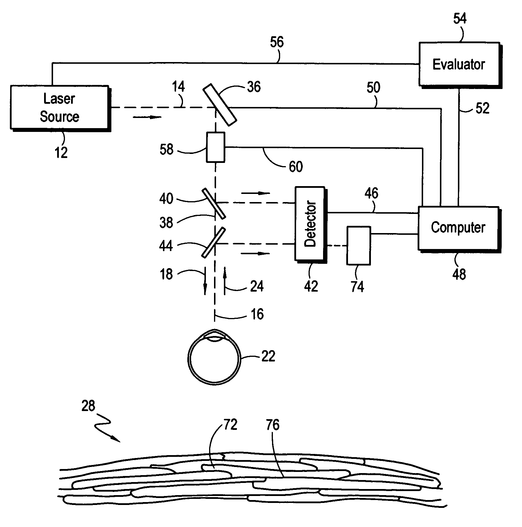
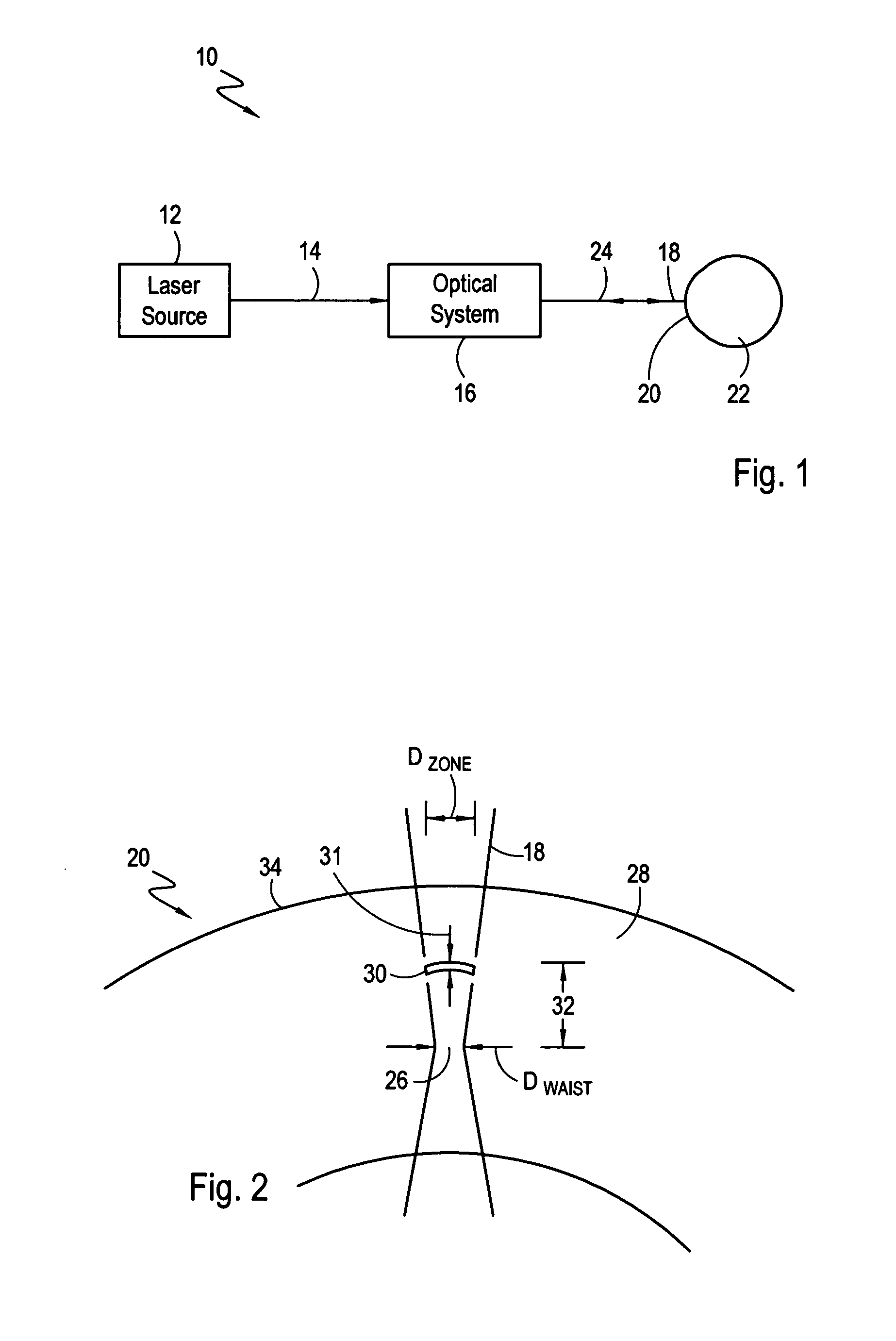
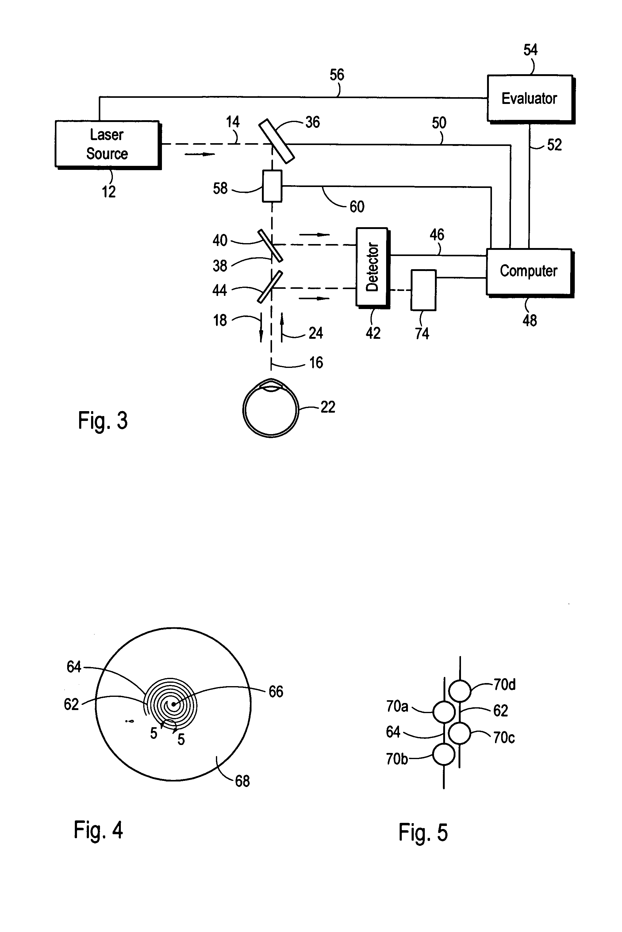
[0027]Referring initially to FIG. 1, an apparatus for intrastromal refractive surgery is shown schematically and is generally designated 10. As shown, the apparatus 10 includes a laser source 12 which, preferably, is capable of generating and controlling a source beam 14 having a continuous train of laser pulses of substantially constant pulse duration and pulse energy. In one embodiment of the apparatus 10, a source beam 14 having a pulse duration of approximately 600 fs and pulse energy of approximately 6 μJ is generated by the laser source 12.

[0028]Continuing with FIG. 1, it can be seen that the apparatus 10 further includes an optical system 16 for forming a shaped laser beam 18 and directing the shaped laser beam 18 toward and into the cornea 20 of an eye 22. Also shown in FIG. 1, reflected light 24 from the eye 22 can be received by the optical system 16. As further detailed below, analysis of the reflected light 24 is useful for several reasons including, but not limited to, ...


PUM


Abstract

A method and apparatus for intrastromal refractive surgery is disclosed wherein tissue at selected locations within the stroma of the cornea is photoablated using a pulsed laser beam. The apparatus includes an optical system for forming a shaped laser beam having a waist at a predetermined distance from the optical system. The pulse duration and pulse energy of the laser beam are selected to cause ablation to occur in front of the waist (i.e. between the waist and the optical system). To achieve this, a pulse energy is used that exceeds the minimum pulse energy required for ablation at the waist. By ablating in front of the waist, a relatively large ablation zone (per pulse) is created (compared to ablation at the waist). Furthermore, while the laser is scanned through the cornea to effectuate a refractive change, the optical system maintains a uniform waist for the laser beam.

Description

[0001]This application is a continuation-in-part of Application Ser. No. 09 / 976,177 filed Oct. 12, 2001, now U.S. Pat. No.6,610,051. The contents of Application Ser. No. 09 / 976,177 are incorporated herein by reference.FIELD OF THE INVENTION[0002]The present invention pertains generally to ophthalmic laser surgery procedures. More particularly, the present invention pertains to laser surgical procedures which are performed to reshape or restructure the cornea of an eye by using photoablation techniques to remove stromal tissue. The present invention is particularly, but not exclusively, useful as a method and system for quickly altering the refractive properties of a cornea with little or no heat damage to non-target corneal tissue.BACKGROUND OF THE INVENTION[0003]It is well known that the refractive properties of the cornea can be altered by the selective removal of corneal tissue. For example, a myopic condition of the eye can be corrected by selectively removing corneal tissue fro...

Claims


Application Information

Patent Timeline
Patent Type & Authority Patents(United States)
IPC IPC(8): A61F9/08A61F9/007A61B18/20A61F9/01A61F9/013
CPCA61F9/008A61F9/00829A61F9/00836A61F9/013A61F2009/0088A61F2009/00848A61F2009/00872
Inventor BILLE, JOSEF
Owner TECHNOLAS PERFECT VISION
Why Eureka
Try Eureka