
Dual-band bandpass filter with stepped-impedance resonators

a stepped-impedance resonator and bandpass filter technology, applied in the direction of resonators, waveguides, electrical equipment, etc., can solve the problems of increasing the cost, increasing the cost, and increasing the circuit area, so as to achieve a wider bandwidth and less loss

Active Publication Date: 2006-09-05
CHANG SHENG FUH +1
View PDF5 Cites 10 Cited by
  • Summary
  • Abstract
  • Description
  • Claims
  • Application Information

AI Technical Summary

Benefits of technology

[0005]Moreover, the coupling sections of the resonators are coupled with each other. One coupling section is coupled respectively with the input end and the output end to filter input signals. Also, the multi-layer broadside-coupled parallel lines structure can be applied to implement dual-band filters with broader bandwidth and less loss.

Problems solved by technology

Hence, it requires higher cost, greater circuit area, and more power consumption.
In practice, it still does not effectively reduce the circuit area and cost.

Method used


Image

  • Dual-band bandpass filter with stepped-impedance resonators
  • Dual-band bandpass filter with stepped-impedance resonators
  • Dual-band bandpass filter with stepped-impedance resonators

Examples


Embodiment Construction

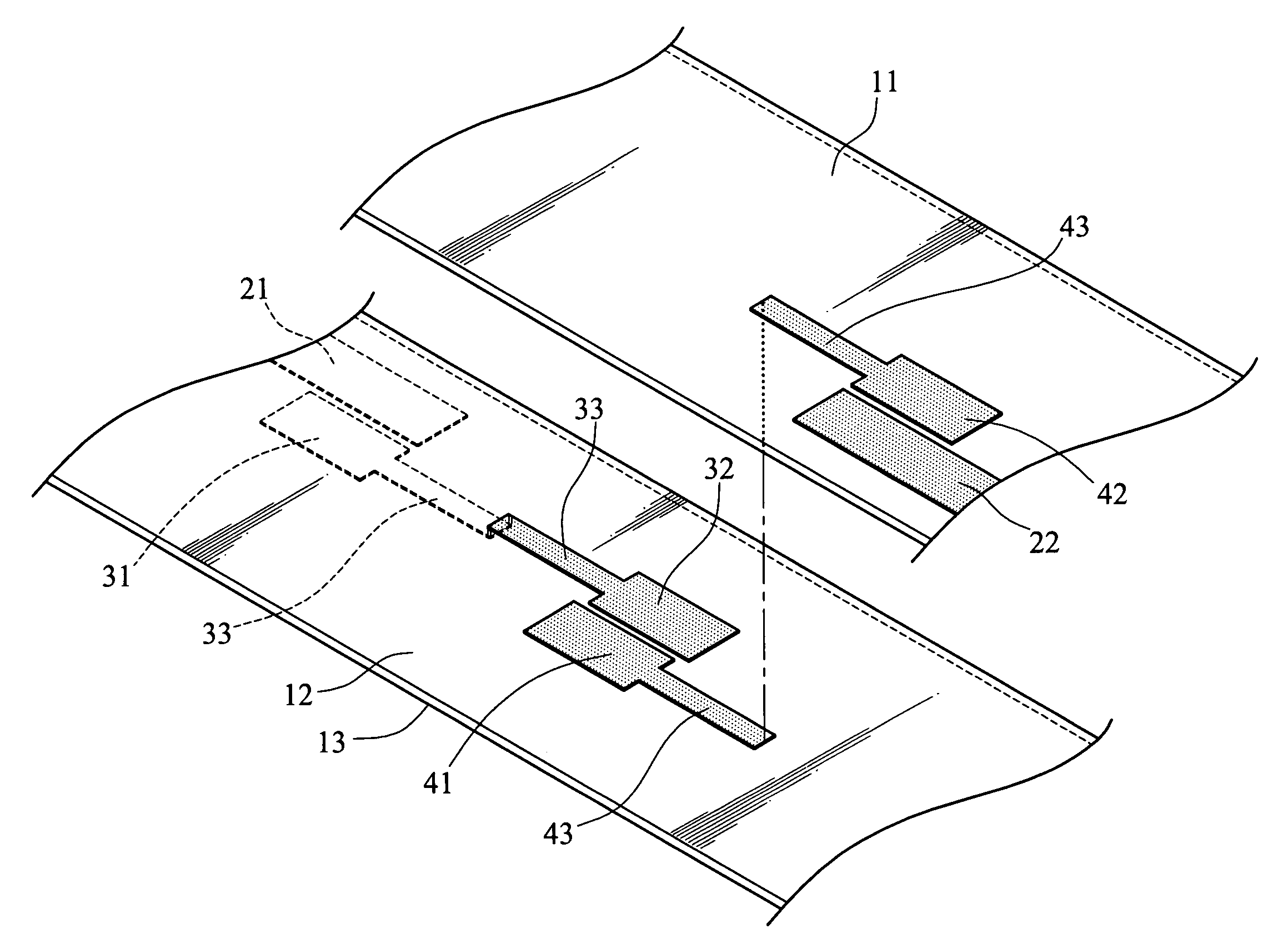
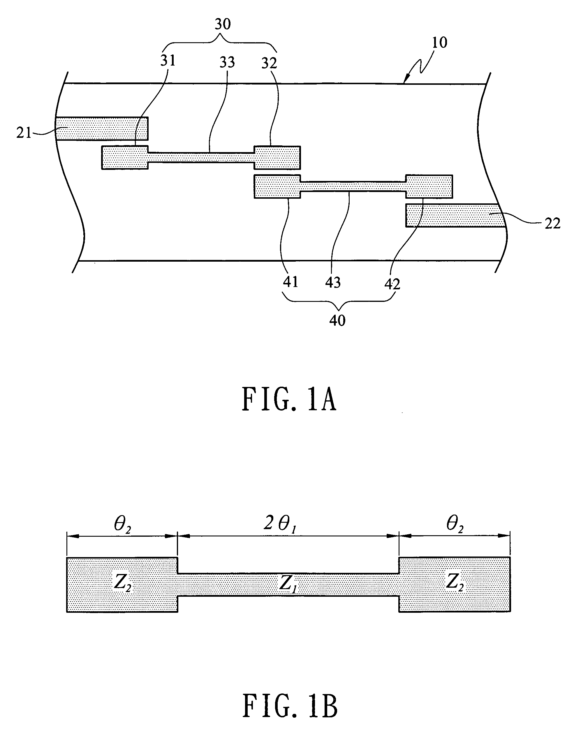
[0014]Referring to FIG. 1A, the dual-band bandpass filter equipped with stepped-impedance resonators according to the invention includes a circuit board 10, an input end 21, an output end 22, a first resonator 30 and a second resonator 40. The input end 21, the output end 22, the first resonator 30 and the second resonator 40 are mounted onto the circuit board 10. The input end 21 receives signals to be filtered. After the signals have been filtered, they are transmitted outwards through the output end 22.

[0015]The first resonator 30 has a first coupling section 31 coupling with the input end 21 and a second coupling section 32 coupling with a third coupling section 41 of the second resonator 40. The second resonator 40 has a fourth coupling section 42 coupling with the output end 22. Hence signals received from the input end 21 are transmitted outwards through the output end 22 through the coupling relationships set forth above. Meanwhile, each of the coupling sections can be in a ...


PUM


Abstract

A dual-band bandpass filter with stepped-impedance resonators uses only one circuit to generate dual-band effect. It adopts the principle of stepped-impedance resonator, which contains a connecting section and two coupling sections. The impedance and electrical length of the connecting section and coupling sections conforms to a selected condition to generate two passbands at desired frequencies. A multi-layer broadside-coupled parallel lines structure may be applied to increase coupling-amount between the parallel lines so that the dual-band bandpass filters have broader bandwidth and less loss.

Description

FIELD OF THE INVENTION[0001]The present invention relates to a dual-band bandpass filter adopted for use in wireless communication and particularly to a dual-band bandpass filter with stepped-impedance resonators.BACKGROUND OF THE INVENTION[0002]Wireless communication has had a tremendous growth in recent years. Developments of wireless transceivers have been gradually directed to multiple bandwidths to provide more flexibility. By means of this technology, users can access different services through one multi-mode, multi-band terminal. In the previous technology, GSM and WCDMA communication systems achieve the dual-band operation by switching two separated transceivers. Such architecture requires two transceivers operating in different frequency. Hence, it requires higher cost, greater circuit area, and more power consumption. To overcome these drawbacks, a so-called concurrent dual-band architecture has been introduced. In this architecture, one transceiver can simultaneously oper...

Claims


Application Information

Patent Timeline
Patent Type & Authority Patents(United States)
IPC IPC(8): H01P1/203
CPCH01P1/20363H01P1/20381H01P1/20372
Inventor CHANG, SHENG-FUHCHANG, SHUEN-CHIENCHEN, JIA-LIANGCHEN, SHIH-CHIEHCHEN, HUNG-CHENGTANG, SHU-FENCHEN, ALBERT
Owner CHANG SHENG FUH
Learn More