Vehicle underbody imaging system

a technology for imaging systems and vehicles, applied in the field of vehicles underbody imaging systems, can solve the problems of time-consuming, inability to view all parts of the vehicle, and -or-miss procedure has questionable value, and achieve the effect of quick image for inspection and/or comparison and reduced number of security personnel

Inactive Publication Date: 2006-09-05
NAVY THE UNITED SATES OF AMERICA AS REPRESENTED BY THE SEC OF THE
View PDF5 Cites 106 Cited by
  • Summary
  • Abstract
  • Description
  • Claims
  • Application Information

AI Technical Summary

Benefits of technology

[0009]Another object is to provide an imaging system and method that are cost effective by speeding up the imaging-inspection process and increasing the number of inspections while reducing personnel requirements.
[0010]Another object is to provide an imaging method and system for mosaicing image portions to build a complete image of a vehicle's underbody with a minimum stationary video cameras.
[0011]Another object is to provide a method and system for quickly imaging underbodies of many moving cars, trucks, marine vessels, and / or aircraft traversing a roadway, marine passageway, and taxiway, respectively for inspection and / or comparison by reduced numbers of security personnel.
[0013]Accordingly, the invention provides a system and method for imaging the underbody of a moving vehicle. A stationary source of radiation radiates energy upwardly onto an underbody of a moving vehicle. A stationary video camera adjacent the radiation source on a roadway has an upwardly facing field of view for creating image signals representative of sequential portions extending the width of the underbody as the moving vehicle passes overhead. A control station activates the camera and radiation source to create the image signals and creates mosaic signals of all of the underbody from the image signals. A graphic display screen provides a mosaic image of the underbody from the mosaic signals. A virtually real-time inspection or a comparison can be made with previously taken underbody images of the same moving vehicle or with vehicle manufacturers' data for the same vehicular model. The underbodies of many moving cars, trucks, marine vessels, aircraft, can be quickly imaged for inspection and / or comparison by reduced numbers of security personnel.

Problems solved by technology

This procedure usually requires several inspectors, is time consuming, and may not enable a full view of all portions of the underbody.
At best, this hit-or-miss procedure has questionable value, and, as fiscal and personnel resources become even more strained, the effectiveness of this course of action is further compromised.

Method used


Image

  • Vehicle underbody imaging system
  • Vehicle underbody imaging system
  • Vehicle underbody imaging system

Examples


Embodiment Construction

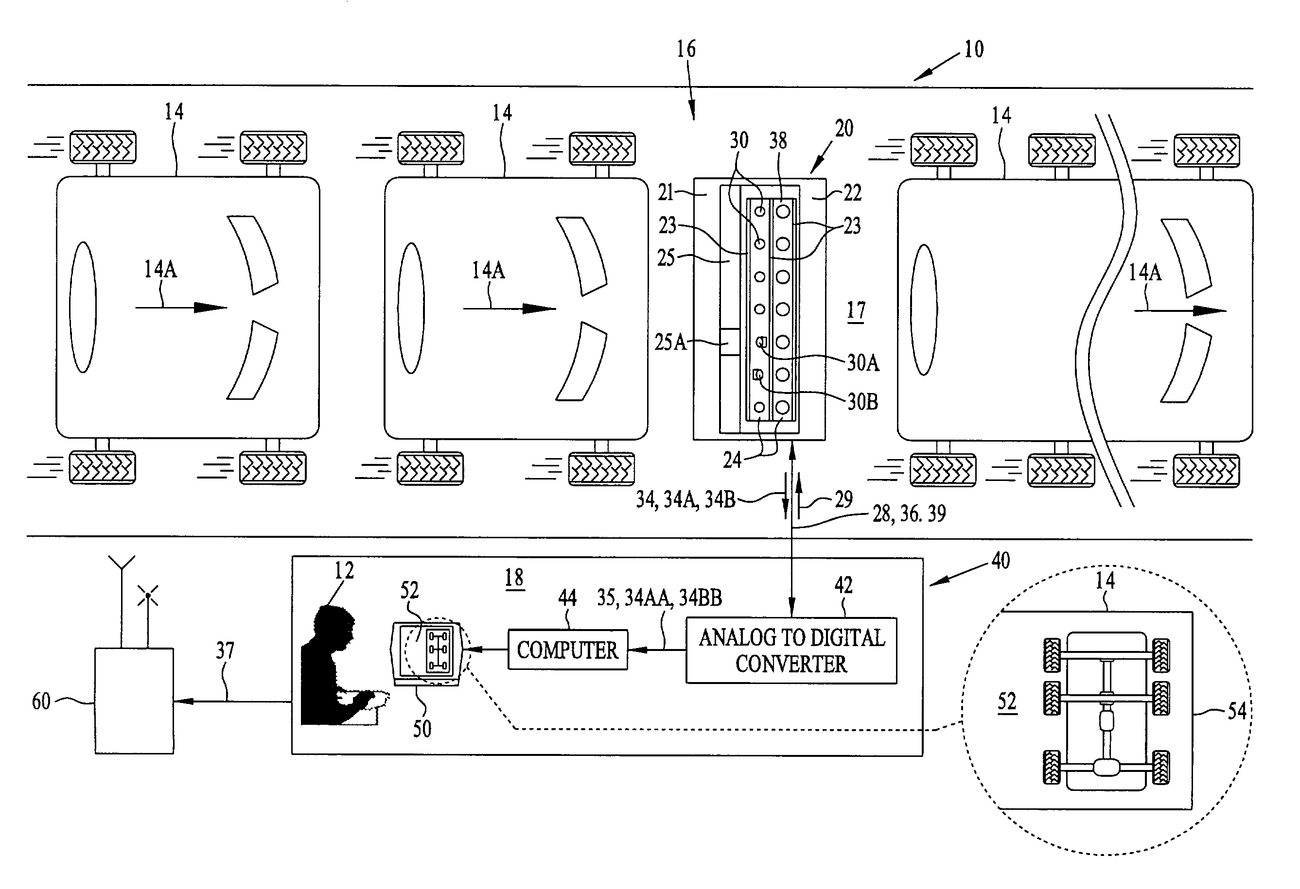
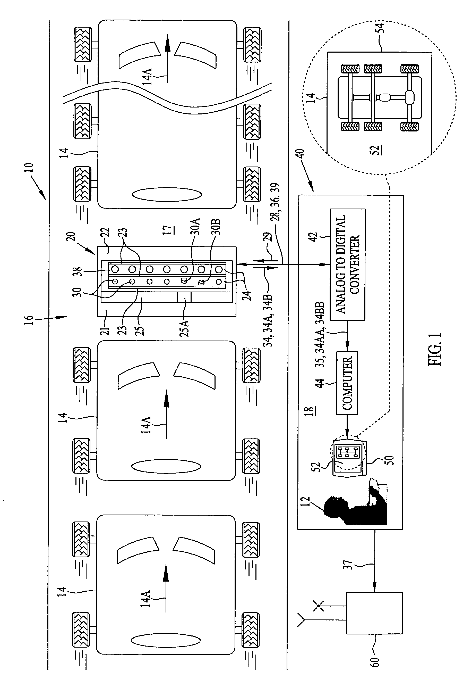
[0018]Referring to FIGS. 1 and 2, vehicle underbody imaging system 10 of the invention permits security personnel 12 to visually inspect the undersides of vehicles 14 moving in the direction indicated by arrows 14A on their roofs as they travel on a roadway 16 past a checkpoint 18. Checkpoint 18 may be anywhere along roadway 16 or could be at an entrance to a secured area. Imaging system 10 creates a complete mosaic image of the underside, or underbody of each vehicle 14 from partial images. These mosaic images can be gathered from all or selected ones of vehicles 14 on roadway 16.

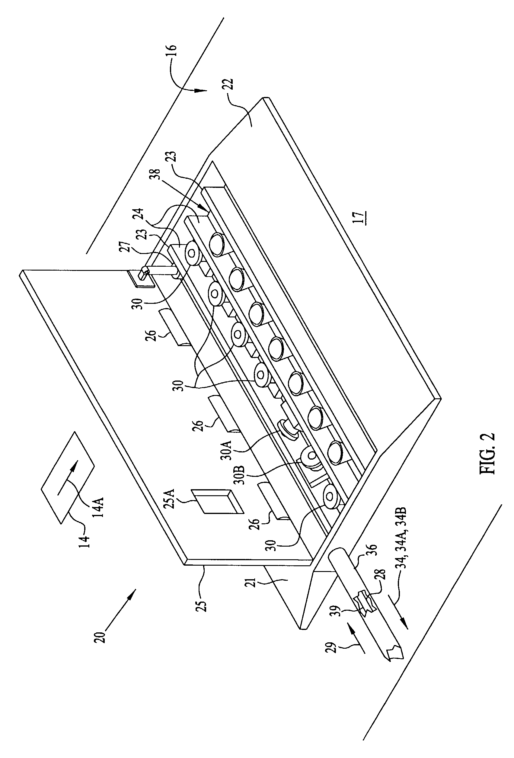
[0019]Vehicle underbody imaging system 10 includes a portable protective housing 20 on roadway 16 that has at least one stationary video camera 30 to provide image signals 34 that are representative of portions of the underbody of each vehicle 14. These image signals 34 are transmitted over a coaxial cable 36 extending from camera 30 to a control station 40 at or remote from checkpoint 18 for observation o...


PUM


Abstract

A system and method for imaging underbodies of moving vehicles have a stationary source of radiation to radiate energy upwardly on underbodies of moving vehicles. A stationary video camera adjacent the radiation source on a roadway has an upwardly facing field of view for creating image signals representative of sequential portions of each underbody as each moving vehicle passes overhead. A control station activates the camera and radiation source to create the image signals and creates mosaic signals of all of each underbody from the image signals. A display screen provides a mosaic image of each underbody from its mosaic signals. A virtually real-time inspection or a comparison can be made with previously taken underbody images of the same moving vehicle or with vehicle manufacturers' data for the same vehicular models. Moving cars, trucks, marine vessels, aircraft, can be quickly imaged for inspection and / or comparison by fewer security personnel.

Description

STATEMENT OF GOVERNMENT INTEREST[0001]The invention described herein may be manufactured and used by or for the Government of the United States of America for governmental purposes without the payment of any royalties thereon or therefor.BACKGROUND OF THE INVENTION[0002]This invention relates to devices and methods for imaging a moving vehicle. More particularly, the imaging device and method of this invention provides mosaic images of the undersides of moving vehicles on a roadway.[0003]Presently, vehicles entering a secure area are randomly selected for inspection. During the inspection, a designated vehicle is stopped, a mirror is rolled beneath the underside, and security personnel make visual inspections. This procedure usually requires several inspectors, is time consuming, and may not enable a full view of all portions of the underbody. At best, this hit-or-miss procedure has questionable value, and, as fiscal and personnel resources become even more strained, the effectivene...

Claims


Application Information

Patent Timeline
Patent Type & Authority Patents(United States)
IPC IPC(8): H04N7/18G06K9/00
CPCG01N21/8806
Inventor CHANDLER, SCOTTDOYLE, CHRIS
Owner NAVY THE UNITED SATES OF AMERICA AS REPRESENTED BY THE SEC OF THE
Why Eureka
Try Eureka