Optical disk adaptable to record at high disk scanning speed, and related apparatus and method
a technology of optical discs and scanning speeds, applied in the field of optical discs, can solve problems such as distortion of recording marks, and achieve the effect of high disc scanning speed and quick start of signal recording
- Summary
- Abstract
- Description
- Claims
- Application Information
AI Technical Summary
Benefits of technology
Problems solved by technology
Method used
Image
Examples
first embodiment
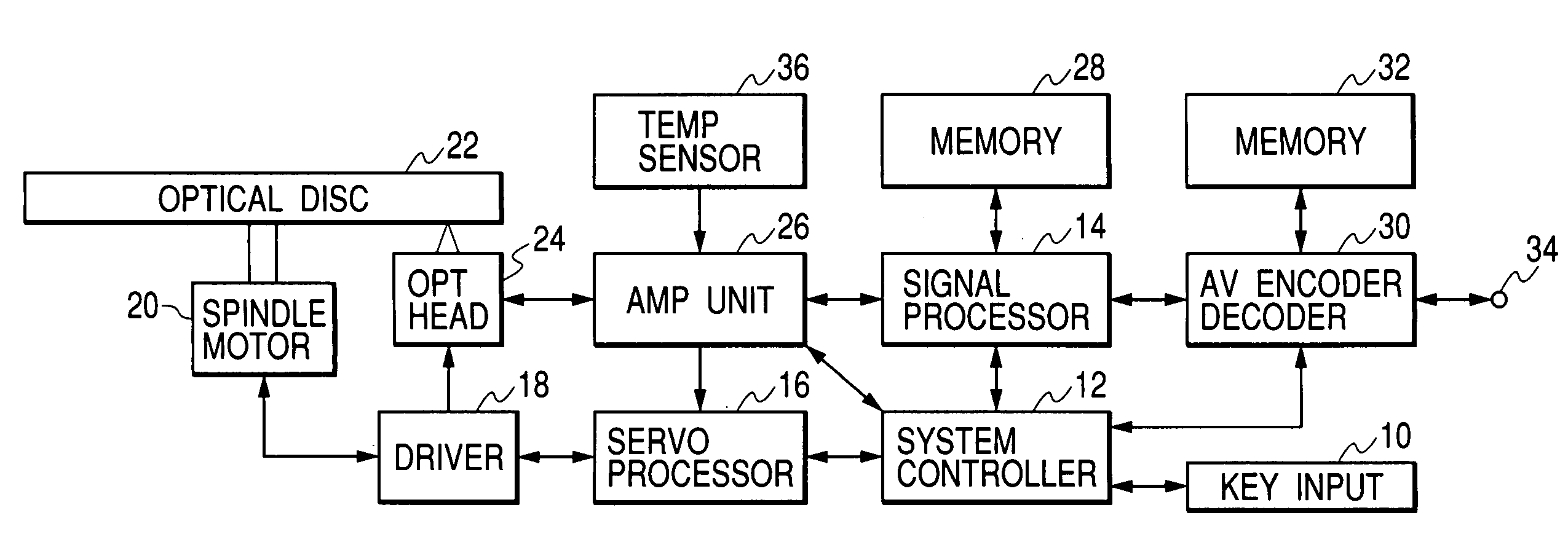
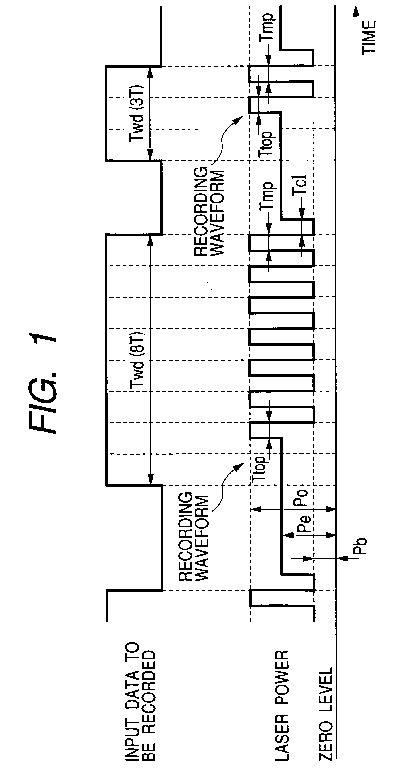
[0046]According to a first embodiment of this invention, a signal is recorded on and reproduced from an optical disc while the disc is scanned by a recording laser beam or a reproducing laser beam. The scanning of the disc by the laser beam is on a CLV (constant linear velocity) basis. The constant linear velocity relating to the scanning of the disc can be selected from a predetermined normal velocity and at least one predetermined high velocity. The normal velocity is equal to, for example, 3.49 m / s. The high velocity is equal to an integer multiple of the normal velocity. The first embodiment of this invention is designed to correct a recording laser beam into an optimal waveform in accordance with the type of an optical disc and a change in the linear velocity relating to the scanning of the disc.
[0047]As shown in FIG. 1, data to be recorded, that is, 8–16 modulation-resultant input data, repetitively change between a high level state and a low level state. The input data contin...
second embodiment
[0124]A second embodiment of this invention is similar to the first embodiment thereof except for design changes mentioned hereafter.
[0125]FIG. 15 shows an optical disc in the second embodiment of this invention. The optical disc in FIG. 15 includes an RMD (recording management data) area and a PC (power calibration) area. The RMD area extends inward of a disc lead-in area. The PC area extends inward of the RMD area.
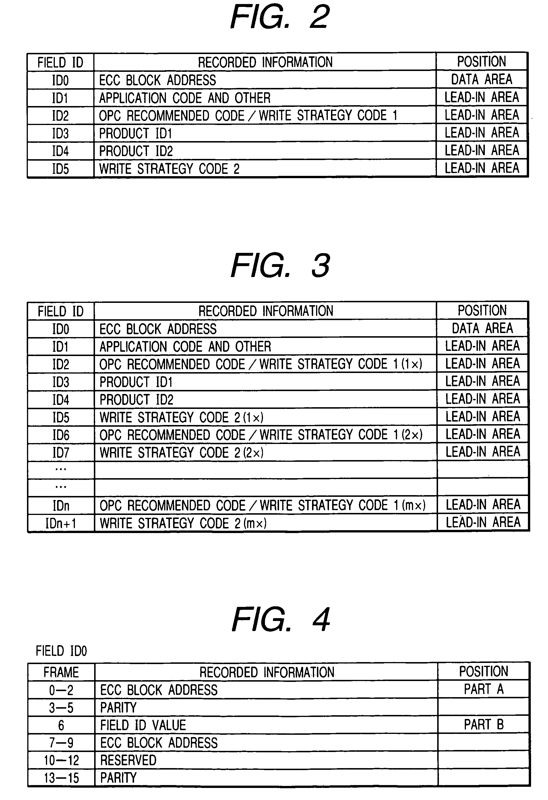
[0126]An information-signal recording and reproducing apparatus in the second embodiment of this invention operates as follows. As in the first embodiment of this invention, the apparatus reproduces information pieces from at least one complete set of fields ID1, ID2, . . . , and IDn+1 on the lead-in area of the optical disc. The system controller 12 in the apparatus derives a recommended recording power level Po, a recommended erasing power level Pe, a recommended bias power level Pb, recommended pulse widths Ttop, Tmp, and Tc1, and a desired disc scanning velocity valu...
third embodiment
[0133]A third embodiment of this invention is similar to the first or second embodiment thereof except for design changes mentioned hereafter. According to the third embodiment of this invention, one lead-in-area LPP-information field, three lead-in-area LPP-information fields, or more lead-in-area LPP-information fields are added as a disc scanning linear velocity is added. Preferably, an information piece representative of a servo system gain depending on a disc scanning linear velocity, an information piece representative of the degree of modulation, and an information piece representative of a jitter value are recorded as lead-in-area LPP-information fields in addition to information pieces of a recording power level, an erasing power level, a bias power level, and strategy values.
PUM
| Property | Measurement | Unit |
|---|---|---|
| velocity | aaaaa | aaaaa |
| wobble frequency | aaaaa | aaaaa |
| frequency | aaaaa | aaaaa |
Abstract
Description
Claims
Application Information
 - R&D
- Intellectual Property
- Life Sciences
- Materials
- Tech Scout
- Unparalleled Data Quality
- Higher Quality Content
- 60% Fewer Hallucinations
Browse by: Latest US Patents, China's latest patents, Technical Efficacy Thesaurus, Application Domain, Technology Topic, Popular Technical Reports.
© 2025 PatSnap. All rights reserved.Legal|Privacy policy|Modern Slavery Act Transparency Statement|Sitemap|About US| Contact US: help@patsnap.com


