Method and apparatus for patterning cards, instruments and documents

a technology for patterning cards and instruments, applied in the field of value cards, can solve the problems of wasting valuable space, so as to achieve the effect of reducing the risk of counterfeiting, and reducing the value of cards

Inactive Publication Date: 2006-09-12
HAN WENYU +1
View PDF16 Cites 21 Cited by
  • Summary
  • Abstract
  • Description
  • Claims
  • Application Information

AI Technical Summary

Benefits of technology

[0015]An advantage of cards made in accordance with the invention is that a significant amount of coded information may be produced without requiring space on the top and bottom surfaces of cards. Leaving the top and bottom surfaces of a card free is significant because these areas are precious real estate used by many card manufacturers as advertising space.

Problems solved by technology

A problem exists with these applications in that there are many instances where the person responsible for checking the validity of the card, such as a cashier, does not actually look at the credit card and simply mechanically “swipes” the card through a card reader, such as a slot reader.
When this occurs, the security features present on the card such as the hologram on the surface of the card and the signature on the back of the card are rendered useless.
Also, to increase the security of the cards more features may be added to make it much more difficult to counterfeit these cards.
A disadvantage of increasing the number of security features placed on the top and bottom surfaces of a card is that it uses up valuable space, which many card manufacturers would prefer to use for advertising.

Method used


Image

  • Method and apparatus for patterning cards, instruments and documents
  • Method and apparatus for patterning cards, instruments and documents
  • Method and apparatus for patterning cards, instruments and documents

Examples


Embodiment Construction

[0049]Applicants' invention resides, in part, in the recognition that an existing technology could be modified and adapted to produce cards which could be encoded and / or patterned without the necessity of using up the surface area of the cards.

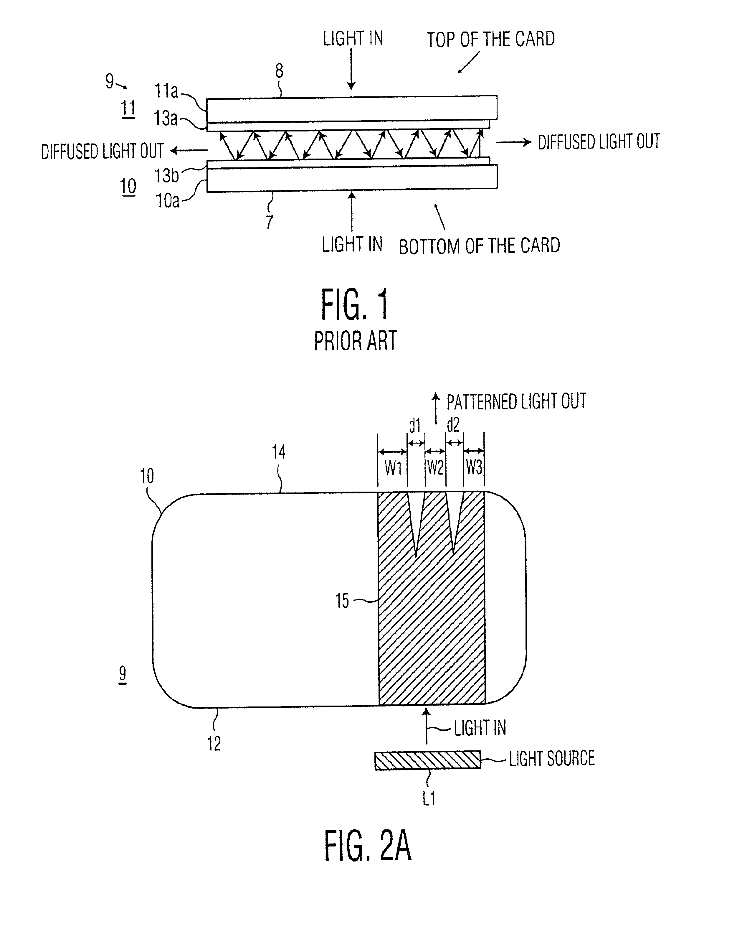
[0050]FIG. 1 shows a cross section of a prior art multi-layered card 9 formed such that the top and bottom layers of the card are spaced from each other to define a channel through which light can pass. The card includes a bottom layer 10 and a top layer 11. Each one of layers 10 and 11 includes an outer layer 10a, 11a, respectively, made of a translucent material. Outer layers 10a, 11a, have an outer surface 7,8, respectively. Each one of layers 10 and 11 also includes an inner layer on which is formed a semi-reflective layer 13a, 13b, respectively, spaced from each other. The semi-reflective layer may be an aluminum compound or an acrylic, or any like material. Light projected onto either one of the outer surfaces (7,8) of the card is captur...


PUM

PropertyMeasurementUnit
heightaaaaaaaaaa
heightaaaaaaaaaa
angleaaaaaaaaaa

Abstract

An instrument (e.g., a card or an optical data storage disc such as a CDROM) embodying the invention includes a pattern formed on or within the instrument, whereby the instrument, when illuminated by a light source, produces a unique output light pattern which can be detected by a photo sensor. The formed pattern may take any number of different and randomly formed shapes ranging from stripes of different size and spacing, as in a bar code, to complex two dimensional shapes and images. The pattern formed between the top and bottom surfaces of an instrument may include randomly distributed light pipes (paths) extending from one side of the instrument to one, or more, other side(s) of the instrument. Alternatively, the pattern formed between the top and bottom surfaces may include a number of “pitted” optical fibers extending from a side of the instrument to a “hidden” region internal to the instrument, which does not extend to any of the sides or surfaces of the instrument. Alternatively, the pattern formed between the top and bottom surfaces of the instrument (e.g., a CDROM) may include opaque optical fibers extending within a region of the instrument. Alternatively, a pattern may be formed on an instrument (e.g., a CDROM) by laser etching or scribing a random pattern on a surface of the instrument.

Description

CROSS REFERENCES TO RELATED APPLICATIONS[0001]This application is a continuation-in-part of U.S. patent application Ser. No. 09 / 190,760 filed on Nov. 12, 1998 now U.S. Pat. No. 6,193,156 and a partial divisional of the material disclosed therein.BACKGROUND OF THE INVENTION[0002]This invention relates to valuable cards, instruments and documents and, in particular to methods and apparatus for patterning or encoding these cards, instruments and documents.[0003]For ease of discussion, the invention will be illustrated using cards such as commonly used plastic cards. However, it should be understood that in the specification to follow and in the appended claims, when reference is made to “cards”, instruments and documents are also included, although not specifically identified as such.[0004]Cards of interest may be used, for example, to identify a person or object and / or they may be used as a value card (i.e. a debit card or credit card) to withdraw money from a machine. Because of the ...

Claims


Application Information

Patent Timeline
Patent Type & Authority Patents(United States)
IPC IPC(8): G06K7/14G06K19/06G06K19/18G11B19/12G11B20/00G11B23/00G11B23/28G11B23/40
CPCG06K19/045G06K19/06046G06K19/086G06K19/18G11B19/12G11B23/40G11B20/00094G11B20/00876G11B23/0042G11B23/281G11B20/00086
Inventor HAN, WENYUZAZZU, VICTOR
Owner HAN WENYU
Why Eureka
Try Eureka