Backlight unit

a backlight unit and light source technology, applied in the field of backlight units, can solve the problems of increased manufacturing costs, increased light loss, and large size, and achieve the effect of reducing costs and high condensation of ligh

Inactive Publication Date: 2006-09-12
LG DISPLAY CO LTD
View PDF8 Cites 64 Cited by
  • Summary
  • Abstract
  • Description
  • Claims
  • Application Information

AI Technical Summary

Benefits of technology

[0021]Accordingly, it is an object of the present invention to provide a backlight unit that is capable of making it possible to highly condense light while reducing costs.

Problems solved by technology

In this case, there are problems in that light loss is increased and manufacturing costs are increased as well.
The conventional backlight unit with such a composition has a problem in that the wall surface of the light guide panel 4 is mirrored or the bright line of the light incident part 20 is visible due to the use of the reverse directional prism sheet 14.
However, because the condensing sheet 16 shown in FIGS. 3 and 4 is so expensive that it is only used for aeronautical or military purposes.
Also, there is a problem in that the backlight unit for highly condensing light, shown in FIG. 4, has a size as large as the area where the prism foil 18 is formed.

Method used


Image

  • Backlight unit
  • Backlight unit
  • Backlight unit

Examples


first embodiment

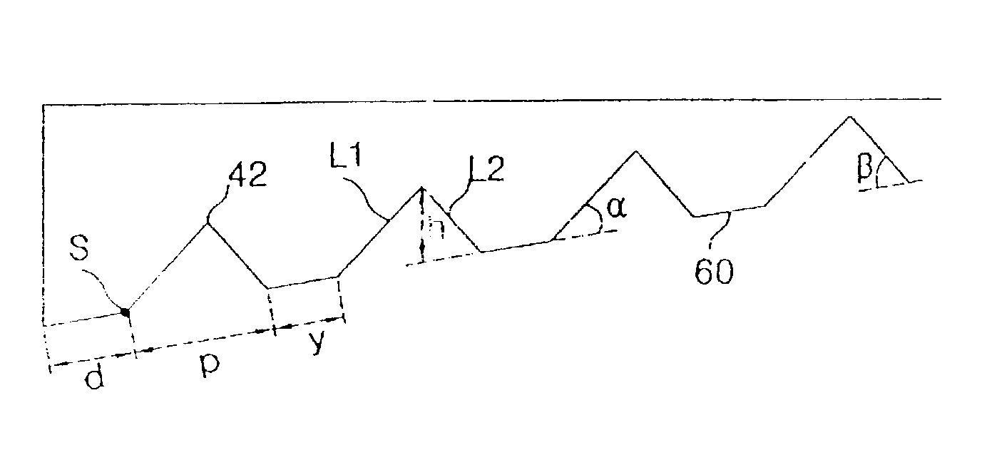
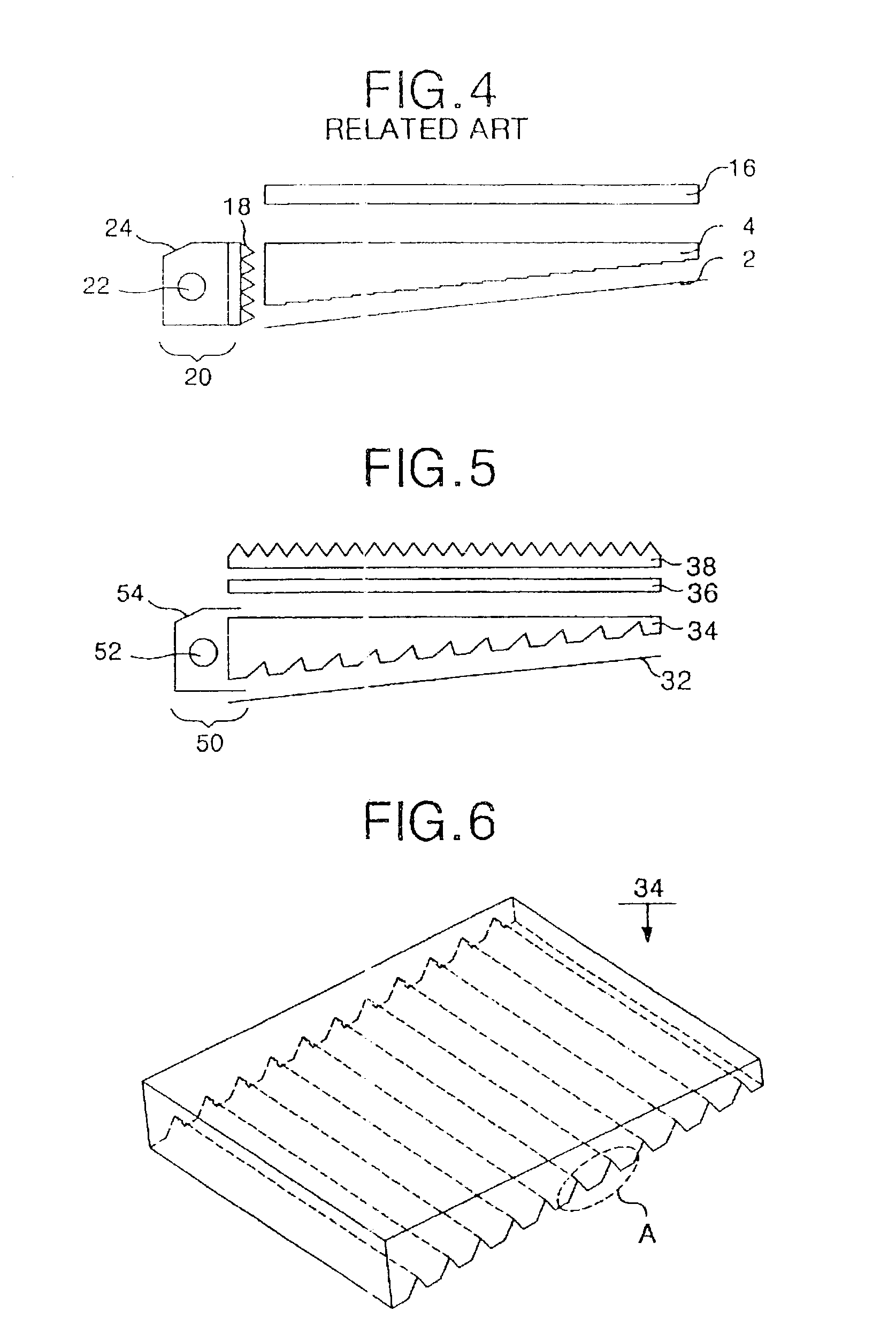
[0070]Referring to FIG. 5, a backlight unit according to the present invention includes a light guide panel 34 for guiding a light beam via a light incident part 50; a reflecting plate 32 located under the light guide panel 34 for reflecting a light beam, which progresses to a lower surface and side surfaces of the light guide panel 34, to the upper surface; a diffusion sheet 36 for diffusing the light beam passed through the light guide panel 34; and a prism sheet 38 for controlling the progress direction of the light beam passed through the diffusion sheet 36.

[0071]The light incident part 50 consists of a lamp 52 for generating a light beam and a lamp housing 54 having the lamp 52 mounted thereon and reflecting the light beam to the light guide panel 34.

[0072]A cold cathode fluorescent lamp is mainly used as the lamp 52, and the light generated from the lamp 52 is incident on the light guide panel 34 through the incident surface located at the side surface of the light guide panel...

second embodiment

[0081]FIG. 9 is a view representing a backlight unit according to the present invention, and FIG. 10 is a diagram more particularly representing the condenser illustrated in FIG. 9.

[0082]Referring to FIGS. 9 and 10, the backlight unit according to the second embodiment of the present invention includes the same components except that condensers 56a and 56b are formed at the light incident part 50 instead of the prism sheet 38 as compared with the backlight unit shown in FIG. 5.

[0083]The light incident part 50 includes a lamp 52 for generating light, a lamp housing 54 installed to cover the lamp 52, and the first and second condenser 56a and 56b for condensing light.

[0084]A cold cathode fluorescent lamp is mainly used as the lamp 52, and the light generated at the lamp 52 is incident on the first condenser 56a. The lamp housing 54 has a reflecting surface inside to reflect the light from the lamp 52 to the first condenser 56a.

[0085]The first and the second condenser 56a and 56b are ...

third embodiment

[0089]FIG. 12 is a view representing a backlight unit according to the present invention.

[0090]Referring to FIG. 12, the backlight unit according to a third embodiment of the present invention includes the same components except that a reflecting part 40 is formed by coating metal on the lower part of the light guide panel 34 instead of the reflecting sheet as compared with the backlight unit shown in FIG. 5.

[0091]The reflecting part 40 has reflecting material coated on the lower surface of the light guide panel 34 where a plurality of engraved patterns are formed. The reflecting part 40 is formed of reflecting material such as silver Ag, aluminum Al etc. The backlight unit with such a reflecting part 40 can be applied to a liquid crystal display with its size below 6 inches.

[0092]The reflecting part 40 reflects the light incident on itself through the lower surface of the light guide panel 34 to the light guide panel 34, thereby reducing light loss.

[0093]In the upper part of the li...


PUM

PropertyMeasurementUnit
angleaaaaaaaaaa
angleaaaaaaaaaa
tilt anglesaaaaaaaaaa

Abstract

There is provided a backlight unit that is capable of making it possible to highly condense light while simultaneously reducing costs. A backlight unit according to an embodiment of the present invention includes a light source for generating light; a lamp housing installed to cover the light source and for reflecting the light; and a light guide panel whereon there are formed a plurality of engraved patterns with a specific gap and a specific depth at the lower surface thereof, and wherein the vertical angle of the engraved pattern, which faces an out-coming surface of the light guide panel, is in a range of 30˜95°. Accordingly, it can be applicable to display panels of various sizes and a picture is improved at the same time. Also, in the backlight unit, it is possible to get rid of at least one of a prism sheet, a diffusion sheet and a reflecting sheet, thereby reducing costs. Moreover, this backlight unit can obtain a highly condensed light by using a light emitting diode that controls the curvature to condense the out-coming light within a specific angle.

Description

[0001]This nonprovisional application claims priority under 35 U.S.C. § 119(a) on patent application No. P2001-84074, filed in Korea on Dec. 24, 2001, which is herein incorporated by referenceBACKGROUND OF THE INVENTION[0002]1. Field of the Invention[0003]The present invention relates to a backlight unit, and more particularly to a backlight unit that is capable of making it possible to highly condense light and reduces costs at the same time.[0004]2. Description of the Background Art[0005]Generally, a liquid crystal display LCD controls the transmittance of a light beam supplied from a backlight unit to display a desired picture on a screen by a liquid crystal display panel consisting of a plurality of liquid crystal cells arranged in matrix type form, and a plurality of control switches for switching the video signals to be supplied to each liquid crystal cell.[0006]In conjunction with FIG. 1, there is explained a backlight unit as follows.[0007]Referring to FIG. 1, a conventional...

Claims


Application Information

Patent Timeline
Patent Type & Authority Patents(United States)
IPC IPC(8): F21V8/00F21V5/02G02F1/13357G02B6/00
CPCG02B6/0025G02B6/0031G02B6/0038G02B6/0071G02B6/005G02B6/0046G02B6/0055G02F1/1335
Inventor SHIN, HYUN HOKIM, JE HONGJEON, SEONG MAN
Owner LG DISPLAY CO LTD
Why Eureka
Try Eureka