
Method and apparatus for cooling a reticle during lithographic exposure

a technology of lithographic exposure and cooling reticle, which is applied in the direction of moving conduit heat exchangers, radiation therapy, printers, etc., can solve the problems of reducing pattern positioning accuracy, thermal distortion is greater, and all the devices on the wafer are unusabl

Inactive Publication Date: 2006-09-12
ASML HLDG NV
View PDF19 Cites 9 Cited by
  • Summary
  • Abstract
  • Description
  • Claims
  • Application Information

AI Technical Summary

Benefits of technology

[0024]A still further advantage of the above embodiments is that the systems and methods allow for the relative motion between the short stroke stage and the long stroke stage (e.g., a working gap, gap, etc.) to be a desired distance (e.g., approximately 1.5 mm) for lithographic tool design.

Problems solved by technology

For a EUV tool, however, where features smaller than 30 nm will be imaged, and where the heat load on the reticle is higher, thermal distortion is a greater problem.
In either case, it is highly desirable not to run liquid on to the short stroke because the vibration introduced by the fluid flow and the dynamic characteristics of the connecting hoses reduce pattern positioning accuracy.
Even a shift of less than 10 nm from a desired to an actual position of each layer of the patterns can render all the devices on a wafer unusable.
This distortion is more troublesome in a EUV system because, as discussed above, there is very little tolerance allowed during the copying of the patterns.
Also, although other systems that operate at longer wavelengths than EUV use transmissive reticles, which are far less sensitive to distortion, they cannot be used with EUV light due to complete absorption.
Unfortunately, the cooling systems vibrate the stages because of the constant flow of liquid.

Method used


Image

  • Method and apparatus for cooling a reticle during lithographic exposure
  • Method and apparatus for cooling a reticle during lithographic exposure
  • Method and apparatus for cooling a reticle during lithographic exposure

Examples


Embodiment Construction

Overview

[0050]Throughout the specification, a reticle is described as the element being cooled by the systems and methods according to the embodiments of the present invention. It is to be appreciated that the systems and methods can function to cool a wafer held to a short stroke wafer stage while the wafer is being exposed. This is done in the same way the systems and methods cool the reticle held to a short stroke reticle stage being used for exposure. Thus, throughout the specification the term reticle can be interchanged with the terms wafer or substrate without departing from the invention. Merely for convenience, most of the description of the systems and methods of the present invention will refer to a reticle.

[0051]Systems and methods of the various embodiments make it unnecessary to circulate a coolant within a short stroke stage. This eliminates vibrations produced by coolant fluid flow through the short stroke stage. Vibrations are detrimental to lithographic performance...


PUM

PropertyMeasurementUnit
poweraaaaaaaaaa
temperatureaaaaaaaaaa
distanceaaaaaaaaaa

Abstract

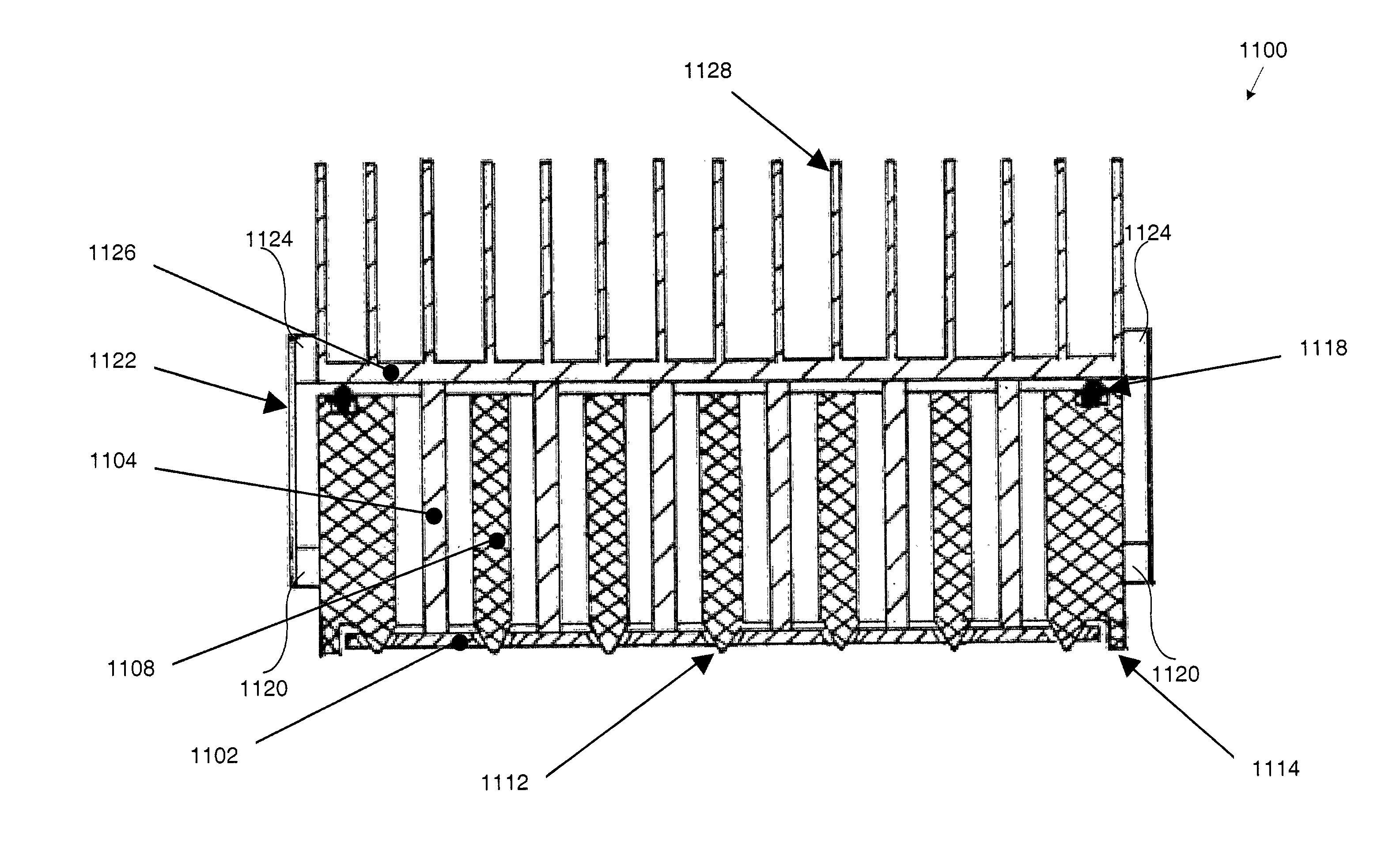
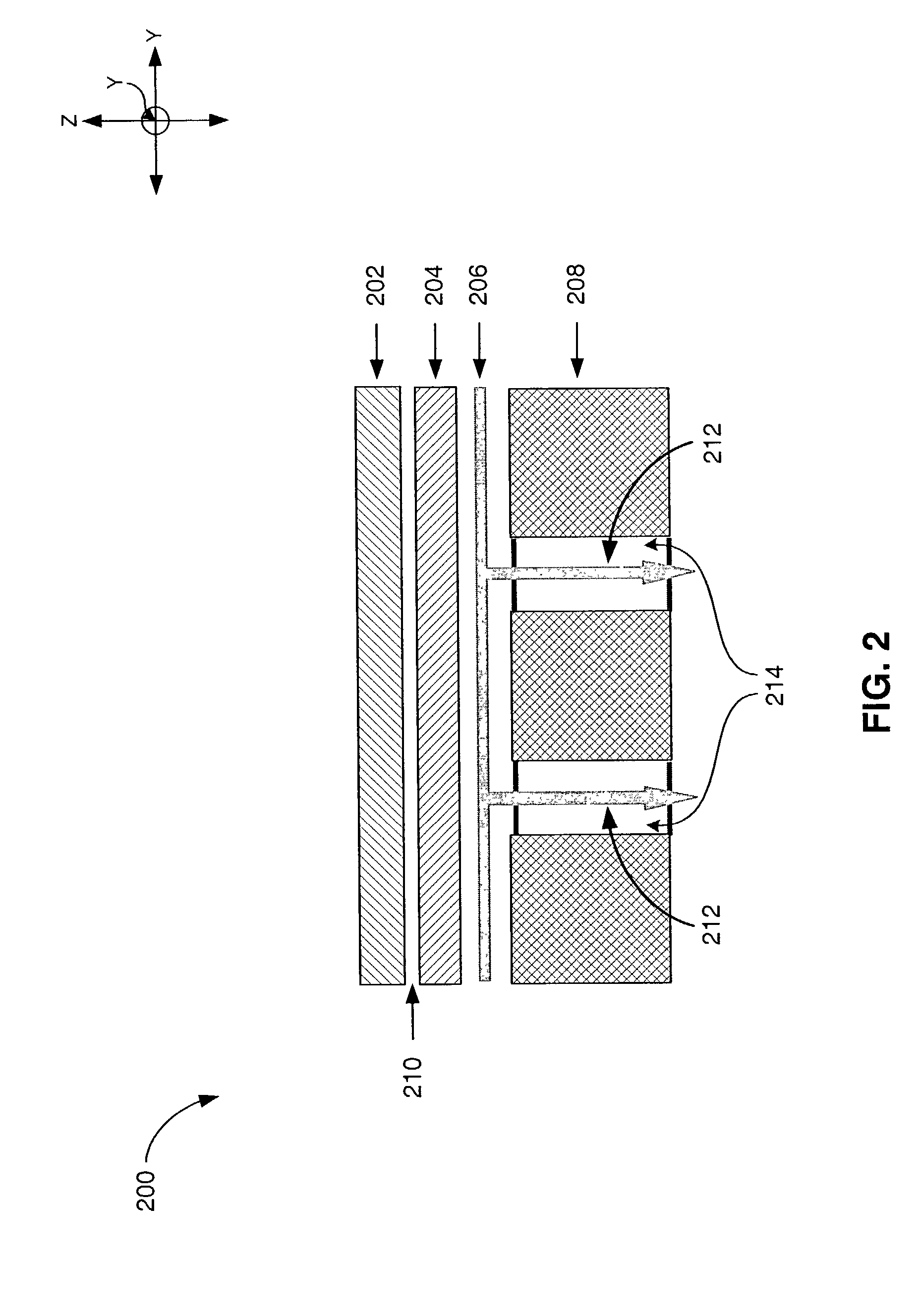
Systems and methods eliminate vibrations produced by coolant fluid flowing through a short stroke stage and prevent change in thermally-induced distortion of the short stroke stage by maintaining the temperature and temperature distribution within the short stroke stage constant regardless of actinic heat load incident on a reticle. This is done by: (1) conducting heat through the reticle and short stroke stage components, (2) radiatively transferring heat from the short stroke stage to a long stroke stage, and (3) using convection and a cooling system to dissipate heat from the long stroke stage. The short stroke stage can be magnetically levitated from the long stroke stage. This way there is no physical contact, but the long stroke stage's movements can still control the short stroke stage's movements. By not physically contacting the long stroke stage, the short stroke stage is not affected by vibrations in the long stroke stage caused by the flowing coolant.

Description

BACKGROUND OF THE INVENTION[0001]1. Field of the Invention[0002]The present invention relates to heat dissipation from a reticle in an extreme ultra violet lithography tool.[0003]2. Background Art[0004]In advanced optical lithography, a master pattern on a substrate, referred to as a reticle, is copied onto a wafer by projecting deep ultra violet (DUV) light through, or reflecting extreme ultra violet (EUV) light off of the reticle, and then passing that light through imaging optics on to a wafer. The requirement to copy on to the wafer sub-micron features requires the wafer and reticle be held in a precise relationship with respect to the imaging optics. In the case of a DUV step and scan lithography tool the reticle is usually held to a reticle stage by vacuum, but for an EUV tool, where a vacuum is required for EUV transmission, electrostatic force is used in place of vacuum. The mechanical interface between the reticle and its stage is called a chuck.[0005]In general, the reticl...

Claims


Application Information

Patent Timeline
Patent Type & Authority Patents(United States)
IPC IPC(8): G03F7/20F25B29/00H01J37/20H01L21/027H01L21/68
CPCG03F7/70716G03F7/70875F28F3/048H01L21/027
Inventor DEL PUERTO, SANTIAGOGALBURT, DANIEL N.MCCULLOUGH, ANDREW W.ROUX, STEPHENOTTENS, JOOST JEROEN
Owner ASML HLDG NV
Learn More