Broad-band low-inductance cables for making Kelvin connections to electrochemical cells and batteries

a low-inductance cable and kelvin technology, applied in the direction of resistance/reactance/impedence, measurement devices, instruments, etc., can solve the problem of significant measurement errors, difficult to adjust the mutual inductance of the transformer, and the effect of canceling the inductance of the cable may only occur over a relatively narrow frequency rang

Active Publication Date: 2006-09-12
MIDTRONICS
View PDF427 Cites 99 Cited by
  • Summary
  • Abstract
  • Description
  • Claims
  • Application Information

AI Technical Summary

Benefits of technology

[0015]A broad-band technique for canceling the distributed inductance of a four-conductor Kelvin contacting cable section comprising two spaced-apart conductor pairs with each conductor pair comprising a current-carrying conductor and a voltage-sensing conductor. A special canceling cable section, also comprising spaced-apart conductor pairs, is connected in tandem with the contacting cable section. Connections between the two cable sections are transposed such that conductors in each conductor pair of the canceling section connect to current-carrying and voltage-sensing conductors from different conductor pairs in the contacting section. The canceling section thereby exhibits a distributed negative mutual inductance that can effectively cancel the distributed positive mutual inductance of the contacting section.

Problems solved by technology

Although the inductance cancellation method of FIG. 4 can be quite effective, there are several problems with its use.
That makes the transformer's mutual inductance a difficult quantity to adjust.
Secondly, the core's hysteresis and eddy current losses introduce resistive terms into the transformer's equivalent circuit that can cause significant measurement errors.
Third, the magnetic permeability of a ferromagnetic core, and hence the transformer's mutual inductance, is frequency dependent.
As a result, effective cancellation of cable inductance may only occur over a fairly narrow range of frequencies.

Method used


Image

  • Broad-band low-inductance cables for making Kelvin connections to electrochemical cells and batteries
  • Broad-band low-inductance cables for making Kelvin connections to electrochemical cells and batteries
  • Broad-band low-inductance cables for making Kelvin connections to electrochemical cells and batteries

Examples


Embodiment Construction

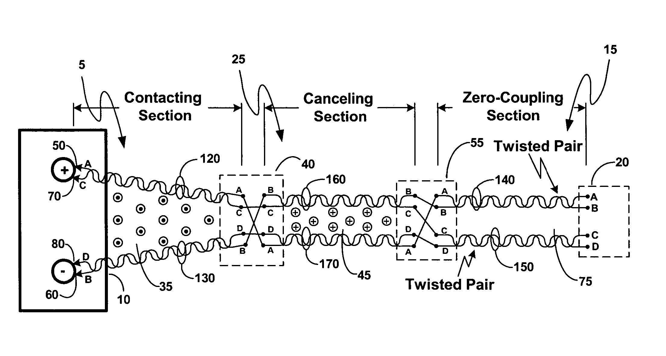
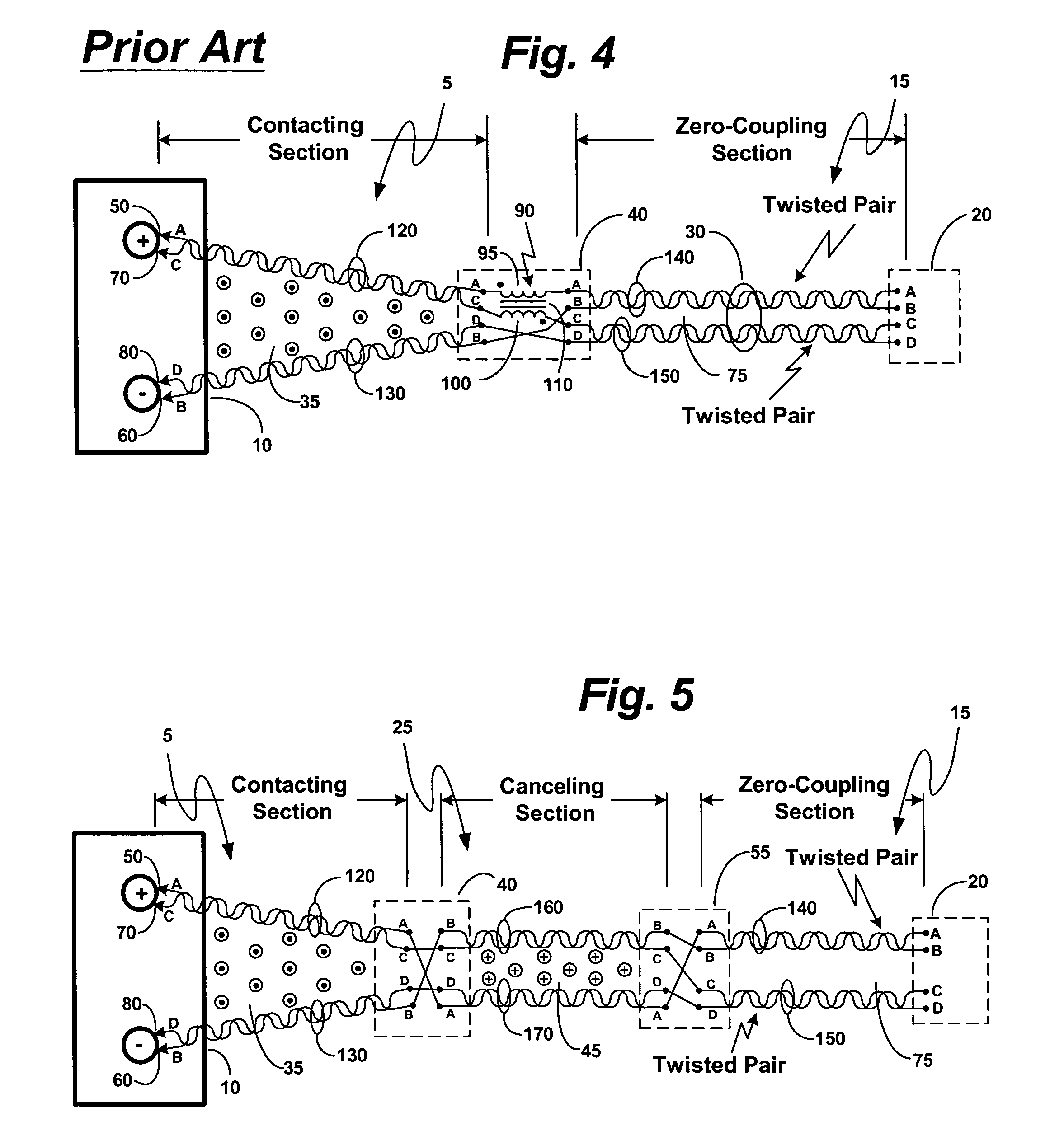
[0028]Consider the invention embodiment disclosed in FIG. 5. This figure depicts Kelvin connections made to battery 10 by means of a conductor arrangement similar to that of FIG. 2, but with an important modification. In FIG. 5, an additional cable section, canceling cable section 25, has been inserted in tandem between cable sections 5 and 15. Canceling cable section 25 comprises two spaced-apart conductor pairs, 160 and 170, each comprising two insulated wires which may, or may not, be twisted together. By virtue of transposed connections made in Y-junction 40 and in cable junction 55, the roles of conductor pairs in sections 5 and 15 are exactly the same as those in sections 5 and 15 of FIG. 2. Conductor pairs in section 25, however, comprise a current-carrying conductor B paired with a voltage-sensing conductor C (pair 160), and a current-carrying conductor A paired with a voltage-sensing conductor D (pair 170).

[0029]Because current-carrying conductors A and B in section 25 are ...


PUM


Abstract

A broad-band technique for reducing the distributed inductance of a four-conductor Kelvin cable is disclosed. A special inductance-canceling cable section is connected in tandem with the cable section contacting the cell / battery. Connections between the two cable sections are transposed such that conductors in each conductor pair of the canceling section connect to current-carrying and voltage-sensing conductors from different conductor pairs in the contacting section. The canceling section thereby exhibits a distributed negative mutual inductance between its current-carrying and voltage-sensing conductors that can effectively cancel the distributed positive mutual inductance introduced by the contacting section.In one embodiment, conductor pairs comprise pairs of insulated wires which may be twisted together. In other disclosed embodiments, conductor pairs comprise shielded coaxial cables.

Description

BACKGROUND OF THE INVENTION[0001]The present invention relates to measuring a dynamic parameter (e.g., impedance, admittance, resistance, reactance, conductance, susceptance) of an electrochemical cell or battery. More specifically, it relates to reducing the effects of cable inductance upon electrical measurements implemented with time-varying signals through Kelvin (i.e., four-point) connections.[0002]Measuring automotive and standby cell / battery parameters with time-varying signals (i.e., measuring dynamic parameters) are now commonly accepted maintenance and diagnostic procedures. (See, e.g., U.S. Pat. Nos. 5,140,269, 6,262,563, 6,534,993, and 6,623,314). Because of the very small impedances of such cells / batteries, Kelvin connections are routinely employed to reduce the influence of contact and interconnecting cable impedance. Kelvin connections make contact with each cell / battery terminal at two separate contact points—one for current and one for voltage. Apparatus for measuri...

Claims


Application Information

Patent Timeline
Patent Type & Authority Patents(United States)
IPC IPC(8): G01R31/04G01R27/28G01R31/36
CPCG01R31/3627G01R31/385G01R1/06G01R31/36
Inventor BERTNESS, KEVIN I.CHAMPLIN, KEITH S.
Owner MIDTRONICS
Why Eureka
Try Eureka