
Method for achieving highly reproducible acceleration insensitive quartz crystal oscillators

a quartz crystal oscillator, highly reproducible technology, applied in the direction of electronic switching, pulse technique, instruments, etc., can solve the problems of insufficient compensation of crystal, insufficient acceleration of quartz crystal, and inability to desire spurious sidebands in output signals, so as to minimize acceleration and vibration response changes, the effect of cost effective and accurately measuring any vibration encountered

Active Publication Date: 2006-09-12
FREQUENCY ELECTRONICS
View PDF6 Cites 27 Cited by
  • Summary
  • Abstract
  • Description
  • Claims
  • Application Information

AI Technical Summary

Benefits of technology

The solution minimizes spurious sidebands and signal degradation, achieving high reproducibility and cost-effective manufacturing, with significant improvements in frequency stability and noise reduction across various vibration conditions.

Problems solved by technology

However, when the same oscillator is subjected to acceleration or to changes in spatial orientation, undesirable spurious sidebands occur in the output signal.
Depending on the particular application of the oscillator, these spurious sidebands, as well as unwanted signal noise, can translate into overall system errors when motion and vibration are encountered.
However, known methods for compensating for the acceleration effects have not resulted in a sufficiently compensated crystal that can be produced with good commercial yields with economies of manufacturing.
The instrument may be moved and turned 90 degrees on its side resulting in the oscillator changing its spatial orientation or positioning by 90 degrees and, thus, resulting in degradation to the oscillator's output signal.
It is believed that no previously known method has ever economically compensated for both the effects of changes in oscillator spatial orientation, i.e., 0 Hz, and for higher vibration frequencies.

Method used


Image

  • Method for achieving highly reproducible acceleration insensitive quartz crystal oscillators
  • Method for achieving highly reproducible acceleration insensitive quartz crystal oscillators
  • Method for achieving highly reproducible acceleration insensitive quartz crystal oscillators

Examples


Embodiment Construction

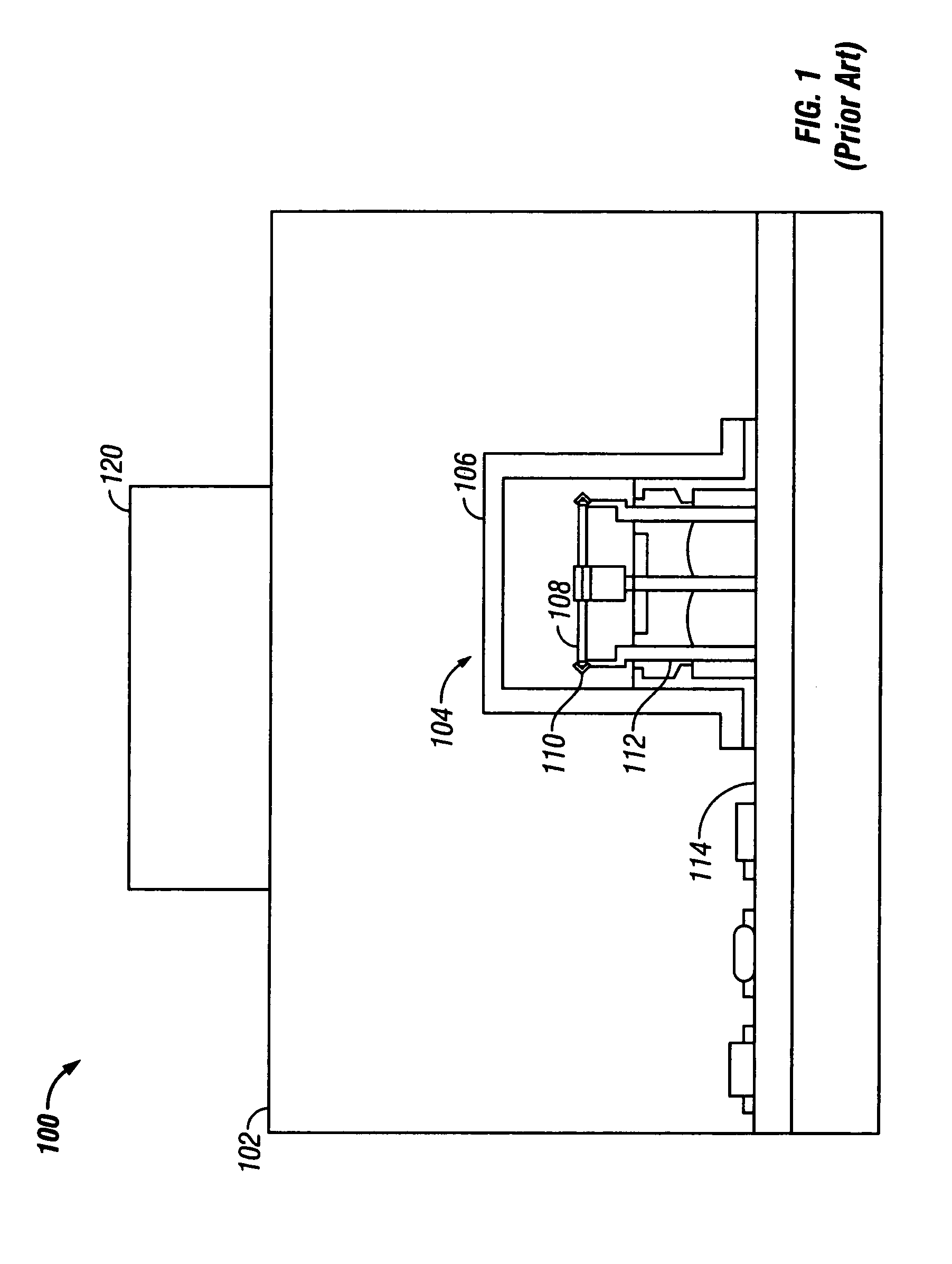
[0028]Referring now to the drawings, wherein like reference numerals denote like or similar elements throughout the drawings, and more particularly to FIG. 1, a prior art oscillator with an accelerator placed outside the oscillator housing is shown. With such oscillators, the compensating techniques used to minimize degradation resulting from vibration-induced sidebands are necessarily dependent on readings from accelerometers that are physically located at some distance from the crystal resonator itself to measure vibration effects. Because the accelerometers are not directly proximate to the oscillator's crystal resonator, the readings from the accelerometer do not directly effect a measure of the vibration being experience by the crystal. In these prior art techniques, after a vibration is detected and inaccurately measured, the compensating scheme or method has traditionally attempted to cancel out a slightly different modulation waveform, or sometimes a significantly different ...


PUM


Abstract

An oscillator and a method for producing an improved oscillator that will generate an accurate frequency when encountering a vibration. The oscillator and method uses a crystal with minimal cross-axis coupling. Further, a first accelerometer produced using MEMS technology is used. The first accelerometer is positioned inside of the oscillator so that the accelerometer accurately measures any vibration encountered by the oscillator. The first accelerometer and the crystal are maintained at constant temperature to minimize phase shifts and gain variations.

Description

RELATED APPLICATIONS[0001]This application is based on U.S. Provisional Patent Application No. 60 / 558,665, filed Mar. 31, 2004.FIELD OF THE INVENTION[0002]The present invention generally relates to quartz crystal oscillators for applications in systems such as precision navigation, radar, commercial and secure communications, space exploration, target acquisition, munitions, and missile guidance, and, more particularly, to a method for producing the quartz crystal oscillators that are used in these systems such that the effects of acceleration or vibration on the output signal of the quartz crystal oscillator in applications is minimized.BACKGROUND OF THE INVENTION[0003]Stress compensated (“SC”) cut quartz crystals have been extensively used as the resonating element in oscillator circuits as a reliable element to generate accurate frequencies. Under static conditions, i.e., an acceleration-free (vibration-free) environment, a well-designed SC-cut quartz crystal oscillator when powe...

Claims


Application Information

Patent Timeline
Patent Type & Authority Patents(United States)
IPC IPC(8): H03B1/04H03B5/32H03B5/04H03B5/36
CPCH03B5/36H03B5/04
Inventor BLOCH, MARTINMANCINI, OLEANDROSTONE, CHARLES
Owner FREQUENCY ELECTRONICS
Learn More