
Method and apparatus for manufacturing large double-sided curved Fresnel lens

a technology of fresnel and lens, which is applied in the field of methods and equipment for manufacturing large, double-sided, curved fresnel lenses, can solve the problems of not being able to produce a mold by which the fresnel grooves are formed on both sides, and it is not easy and realistic to develop such a large ultra-precise machining apparatus,

Inactive Publication Date: 2006-09-12
RIKEN
View PDF11 Cites 41 Cited by
  • Summary
  • Abstract
  • Description
  • Claims
  • Application Information

AI Technical Summary

Benefits of technology

"The present invention provides a method and apparatus for manufacturing a large double-sided curved Fresnel lens with high transparency. The method involves performing ultra-precise three-dimensional machining on a material to make an upper mold and a lower mold, and then pressing the thermoplastic resin plate between the molds to curve it and transfer both lens surfaces to the resin plate. The apparatus includes a rotary table for high-speed machining, a machining tool, and an ultra-precise machining device. The invention allows for efficient manufacturing of the double-sided curved Fresnel lens with high performance."

Problems solved by technology

Therefore, it is not easy and realistic to develop such a large ultra-precise machining apparatus.
However, there has not been a mold by which the Fresnel grooves are formed on both sides of a curved plate.
Accordingly, it has been difficult to produce a curved lens having Fresnel grooves on both sides thereof.

Method used


Image

  • Method and apparatus for manufacturing large double-sided curved Fresnel lens
  • Method and apparatus for manufacturing large double-sided curved Fresnel lens
  • Method and apparatus for manufacturing large double-sided curved Fresnel lens

Examples


first example

[0057]Next, a first example of the present invention will be described.

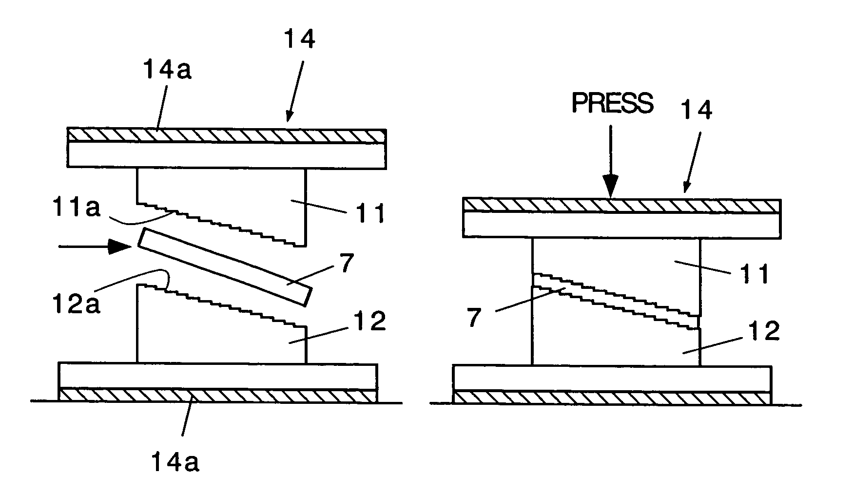
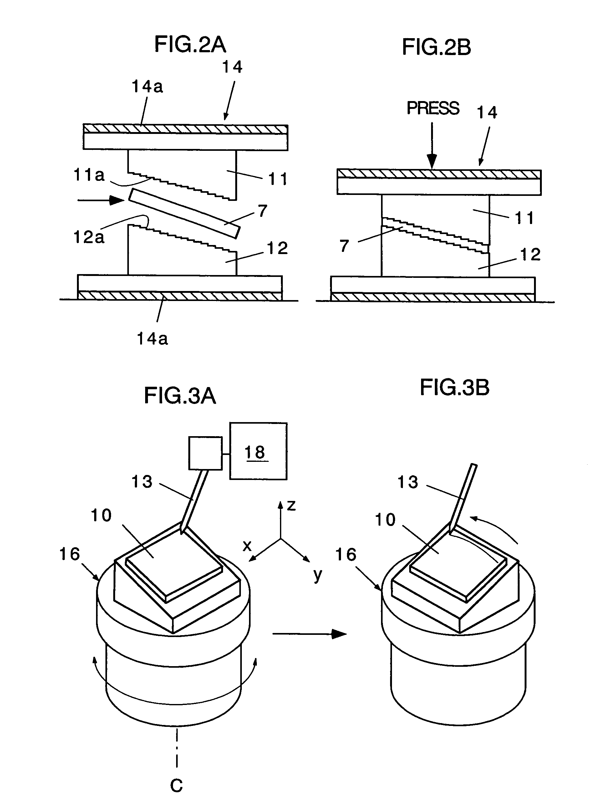
[0058]A lens material of the large, double-sided, curved Fresnel lens shown in FIG. 1A is an ultraviolet ray transparency grade plate made of PMMA (polymethylmethacrylate) and having a thickness of 20 mm. In this example, a plate material made of oxygen-free copper was three-dimensionally machined with very high accuracy to fabricate a mold 11, and then, this mold 11 was used to transfer Fresnel surface on a lens material for a tablet slice segment lens 3 by taking advantage of the thermoplastic property of the lens material.

[0059]An overall size of the tablet slice segment lens 3 was cut out from the PMMA material, and the cut lens material for the segment lens 3 was preheated in a furnace. Thereafter, the heated lens material was thermally pressed by using the mold 11 attached to the hot press machine to transfer the spherical surface and the Fresnel lens shape on the lens material. Then, the lens material was ...

second example

[0078]In addition to the first example, another hot press molding experiment was performed in which materials other than PMMA (polymethylmethacrylate) was used as a transparent thermoplastic resin plate 7. TPX (polymethylpentene made by Mitui Kagaku Inc.), Cytop (a fluorinated resin made by Asahi Garasu Inc.), and ZEONEX (cycloolefin resin made by Nihhon Zeon Inc.) were used as the materials other than PMMA.


PUM

PropertyMeasurementUnit
diameteraaaaaaaaaa
diameteraaaaaaaaaa
radiiaaaaaaaaaa

Abstract

A method of manufacturing a large double-sided curved Fresnel lens. The method includes a machining step (A) of performing ultra-precise three-dimensional machining on an upper mold and a lower mold to each have an upper transfer surface and a lower transfer surface engaging an upper surface and a lower surface of a thermoplastic resin plate, respectively. Further, the method includes a hot press molding step (B) of pressing the thermoplastic resin plate between the upper and lower molds by a predetermined pressure with the resin plate being held at a temperature higher than a softening temperature thereof and lower than a melting temperature thereof so that the thermoplastic resin plate is curved, and both lens surfaces for the double-sided Fresnel lens are respectively transferred to an upper surface and a lower surface of the thermoplastic resin plate.

Description

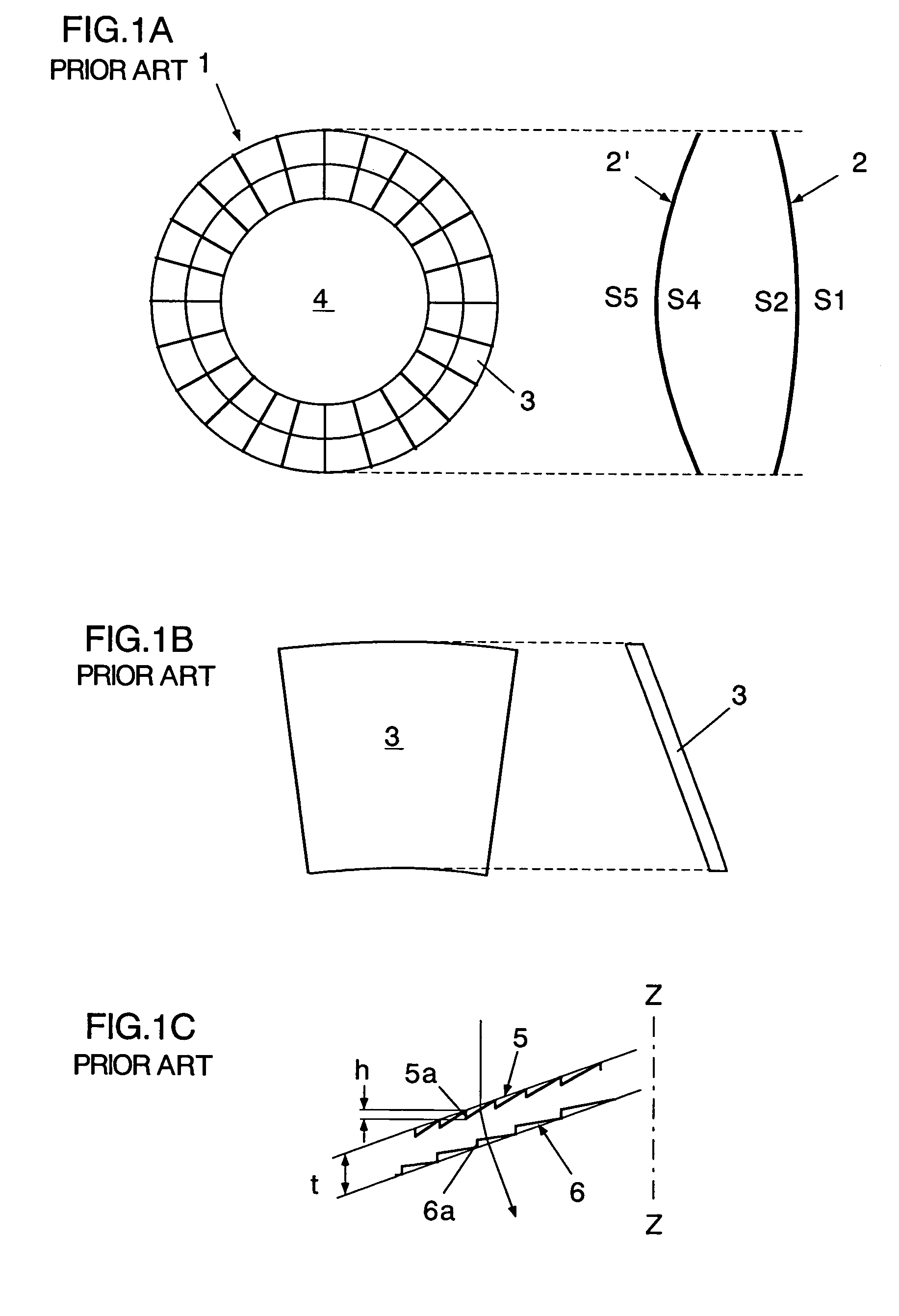
[0001]This is a National Phase Application in the United States of International Patent Application No. PCT / JP02 / 12628 filed Dec. 3, 2002, which claims priority on Japanese Patent Application No. 370052 / 2001 filed Dec. 4, 2001. The entire disclosures of the above patent applications are hereby incorporated by reference.BACKGROUND OF THE INVENTION[0002]1. Field of the Invention[0003]The present invention relates to a method and apparatus for manufacturing a large, double-sided, curved Fresnel lens that has a Fresnel groove on each surface.[0004]2. Description of the Related Art[0005]FIG. 1A schematically shows a large, double-sided, curved Fresnel lens. It is proposed to use an optical system having two large, double-sided, curved Fresnel lenses 2 and 2′ for imaging in-order to observe light (Cherenkov radiant ray) generated from high-energy particles at the time the high-energy particles fall in the atmosphere from outside the earth. By observing Cherenkov radiant ray, it is possibl...

Claims


Application Information

Patent Timeline
Patent Type & Authority Patents(United States)
IPC IPC(8): G02B3/08B29C43/02B29C43/36B29D11/00
CPCB29C43/021B29C43/36G02B3/08B29D11/00269B29L2011/005B29C2043/5841
Inventor OHMORIUEHARA, YOSHIHIROUENO, YOSHIYUKIYAMAGATA, YUTAKAMORITA, SHINYA
Owner RIKEN
Learn More