Write head demagnetizer

a demagnetizer and writing head technology, applied in the field of inductive magnetic heads, can solve problems such as the decay of the current of the head, and achieve the effect of simple and inexpensiv

Active Publication Date: 2006-09-12
AVAGO TECH INT SALES PTE LTD
View PDF25 Cites 16 Cited by
  • Summary
  • Abstract
  • Description
  • Claims
  • Application Information

AI Technical Summary

Benefits of technology

[0007]According to one embodiment of the invention, a circuit including a ramp-down voltage source is connected by switches to an H-bridge circuit. When the circuit is engaged, it repeatedly alternates the polarity of the head current, while also causing the head current to decay. This gradually brings the gate voltages of the output drivers of the H-bridge circuit to the supply voltages, thereby demagnetizing the inductive write head. The embodiment provides a simple and inexpensive circuit that can be added to an H-bridge circuit in order to clear an inductive head.

Problems solved by technology

When the circuit is engaged, it repeatedly alternates the polarity of the head current, while also causing the head current to decay.

Method used


Image

  • Write head demagnetizer
  • Write head demagnetizer
  • Write head demagnetizer

Examples


Embodiment Construction

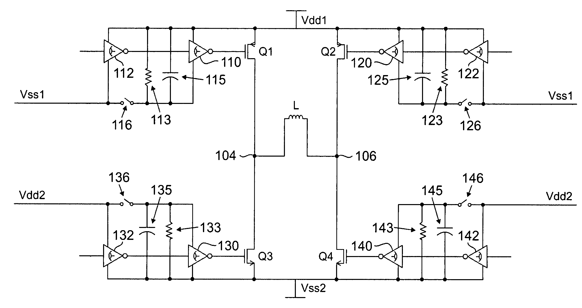
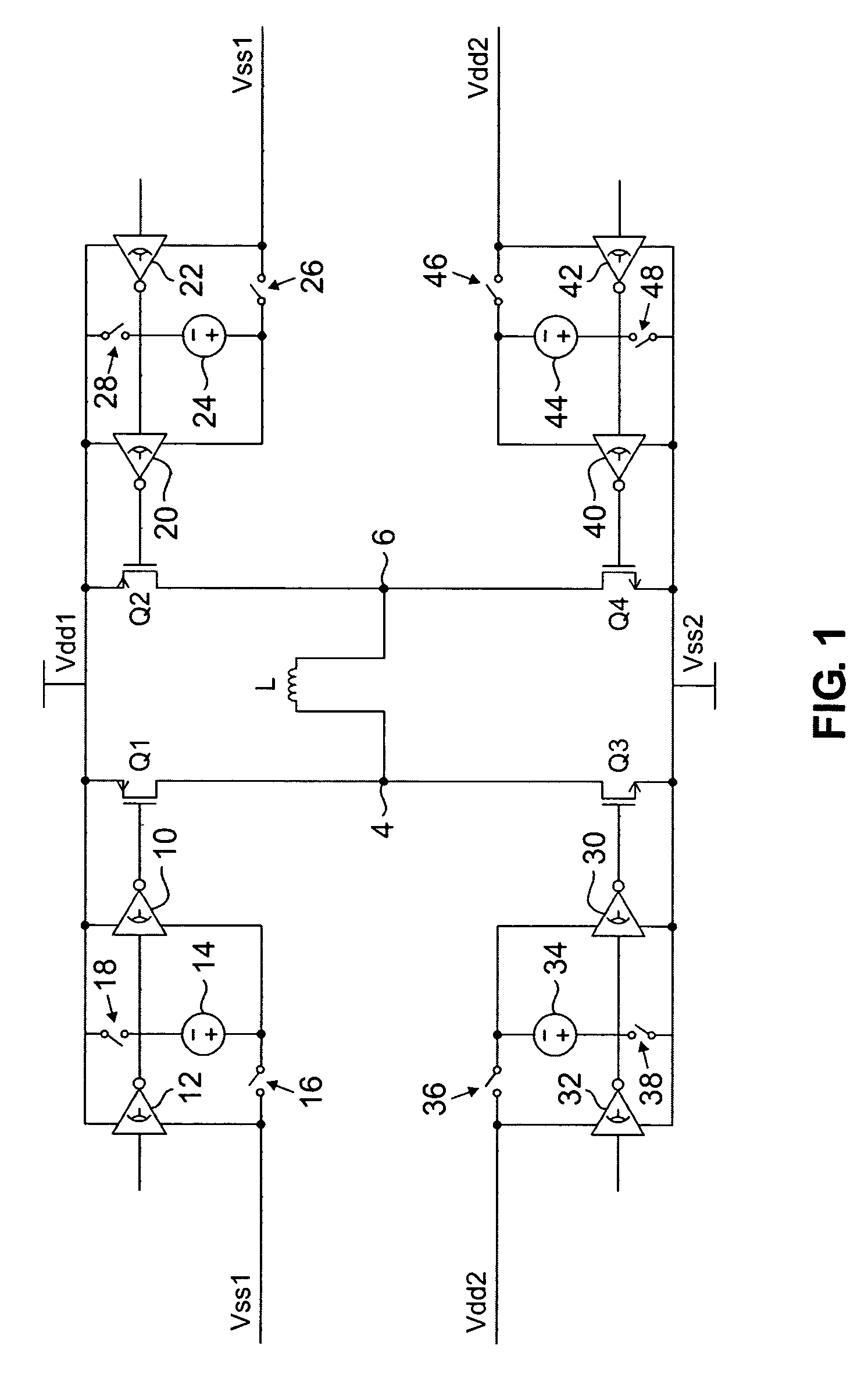
[0015]FIG. 1 illustrates an H-bridge circuit comprising transistors Q1, Q2, Q3 and Q4 connected in the form of an H, with transistors Q1 and Q3 forming one leg of the H, transistors Q2 and Q4 forming the other leg of the H, and with inductive coil L of the inductive magnetic head connected across the center of the H through load terminals 4 and 6. In the embodiment illustrated in the drawing, transistors Q1 and Q2 are PMOS field effect transistors having their sources connected to a positive voltage source Vdd1 and transistors Q3 and Q4 are NMOS field effect transistors having their sources connected to negative voltage source Vss2. The drains of transistors Q1 and Q3 are connected together and to load terminal 4 and the drains of transistors Q2 and Q4 are connected together and to load terminal 6.

[0016]The gates of transistors Q1–Q4 are connected to logic inverters. The gate of transistor Q1 is connected to the output of inverter 10, the gate of transistor Q2 is connected to the ou...


PUM

PropertyMeasurementUnit
currentaaaaaaaaaa
time constantaaaaaaaaaa

Abstract

A demagnetizer for an inductive load having a driver circuit including at least one transistor and a ramp-down voltage source switchably connected to the driver circuit, so that when the ramp-down voltage source is connected to the transistor, it drives the voltage of the transistor below its threshold voltage.

Description

BACKGROUND[0001]This invention relates to inductive magnetic heads, and particularly to eliminating or reducing remnant magnetization and residual flux in the inductive magnetic head.[0002]Inductive magnetic heads are commonly used in magnetic disk drives for writing data to magnetic disks. The magnetic head is operated by driving a write current through the inductive coil of the magnetic head, and reversing the direction of the current to reverse the magnetic field generated by the head. Field reversals in the head induce changes in magnetic dipoles on the disk to represent data. While several types of current driver circuits are commonly used to drive current in opposite directions through the coil, one common circuit is an H-bridge circuit. An H-bridge circuit employs four transistor switches operated to direct write current through alternating pairs of the switches of the circuit.[0003]For optimal performance, it is necessary to periodically clear the inductive head by removing ...

Claims


Application Information

Patent Timeline
Patent Type & Authority Patents(United States)
IPC IPC(8): G11B5/02
CPCH01F13/006G11B5/465G11B5/127G11B5/17
Inventor FANG, HAOKUEHNE, STEPHEN CARL
Owner AVAGO TECH INT SALES PTE LTD
Why Eureka
Try Eureka