Distance division multiplexing

a technology of distance division and multiplexing, applied in the field of communication of information, can solve the problems of general unobvious how any form of distance determination could help, and the current technology is especially worse off, and is useless for separation itsel

Active Publication Date: 2006-09-12
GURUPRASAD VENKATA
View PDF4 Cites 17 Cited by
  • Summary
  • Abstract
  • Description
  • Claims
  • Application Information

AI Technical Summary

Benefits of technology

[0036]Thus, with subband processing, near perfect separability can be assured in all cases, without a fundamental need for autocorrelation or other techniques that would involve signal modulation or content. It is generally desirable, however, to keep the subbands as wide and as few in number as possible, however, because each subband entails shifting, filtering and reverse shifting operations, adding linearly to the complexity of the receiver. It would be generally preferable, therefore, to keep n small, and indeed as close to 1 as possible.
[0037]The secondary object of detecting interference and estimating the source distribution may be achieved by a simple variation of this procedure, comprising, after Step B, the alternative steps of
[0061]These selection and detection functions may also be combined in a receiver, by the use of separate detection and source separation modules, each containing its own instances of both the subband filters S and the frequency spreading shift mechanisms H. In such a receiver, the detection module may use relatively narrow subbands to dynamically determine the coarsest subband partitioning of the signal spectrum to simplify the operating configuration of source selection module, and to thus ensure better performance or lower the total power consumption. Another variation would be to keep the inventive selection module on standby, so as to only activate it in the presence of interference. The onset of interference may be detected automatically using the inventive Steps C′ and D′, simplistically without partitioning into subbands, or more particularly with subbands, or more accurately using a single scanning subband, as in Steps A* through C*. An alternative arrangement could also be employed for the interference detection in order to activate the inventive source selection procedure. In the case of audio or video communication, the inventive signal selection procedure may even be manually activated or turned off based on perception of interference.

Problems solved by technology

Such an ideal receiver is unachievable by Shannon's theory, but current technology is especially worse off with respect to the criterion of interference, because it splits the available physical bandwidth in some way to keep the signals from multiple sources separate all the way.
The main challenges are directivity and range selection.
It is in fact generally unobvious how any form of distance determination could help in signal selection or source isolation.
The encoded information would be generally available only after the signals are separated, and would be thus useless for the separation itself.

Method used


Image

  • Distance division multiplexing
  • Distance division multiplexing
  • Distance division multiplexing

Examples


Embodiment Construction

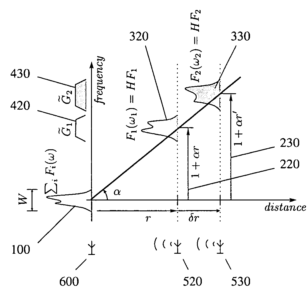
[0081]FIG. 1 illustrates the inventive procedure for separating signals received from sources at different distances from the receiver, using a graph of the spectral shift as a function of distance. Incoming signals of spectra F(w) and F′(w), from sources [520] and [530] at distances r and r′=r+δr, respectively, from the receiver [600] located at the origin of the graph are assumed to ordinarily occupy the same frequency band W. The two signals would ordinarily be received together as the combined signal ΣjFj(w)≡{Fj} [100] and interfere with each other's reception at the receiver.

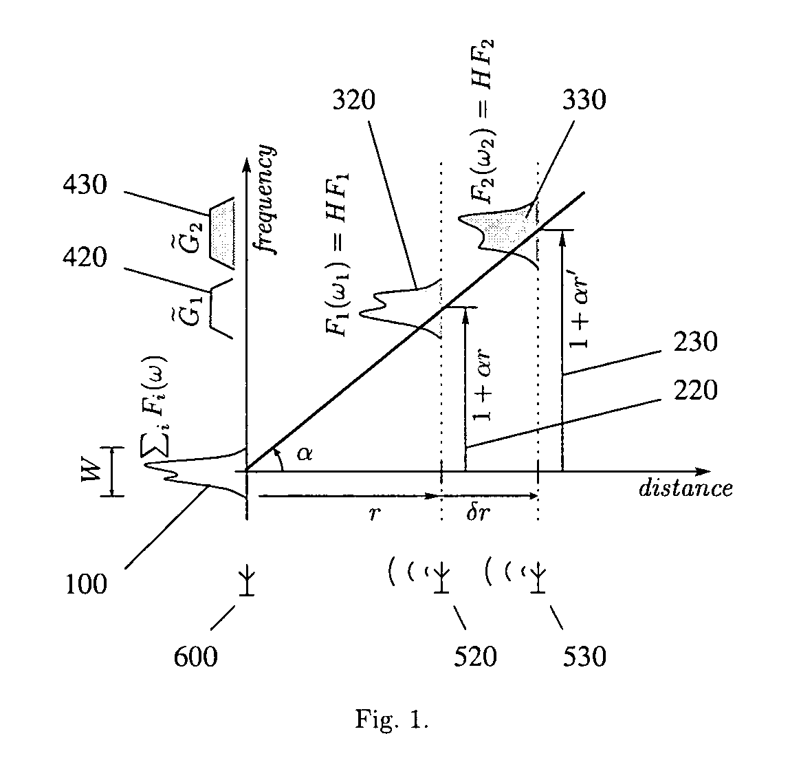
[0082]By applying Step B of the inventive procedure as given in the Summary, the receiver causes the spectra of these component signals to be shifted in proportion to the source distances using the method described in the copending application, i.e. by frequency factors (1+αr) [220] and (1+αr′) [230]. The component spectra then occupy the shifted bands F1(w1)≡H(α)F1(w)≡HF1 [320] and F2(w1)≡H(α)F2(w)≡HF2 [33...


PUM


Abstract

A general method for extracting an electromagnetic or other wave-propagated signal of a desired source from the overall received waveform containing the sum of signals from a multitude of such sources, independently of signal contents and modulation. The method comprises the steps of first expanding the spectrum of the received sum of signals in proportion to their source distances so as to spectrally isolate the signal from the desired source, selecting the isolated signal spectrum using a bandpass filter, and finally, spectrally compressing the selected signal back to its original band of frequencies. The distance dependent expansion is performed by scanning the phase gradient of the signal spectrum. Related method for computing the spread of source distances by measuring low and high frequency bounds of the expanded sum of signals or subbands, or by plotting the expanded sum of signals or subbands on a graph.

Description

CROSS REFERENCE TO RELATED APPLICATIONS[0001]This application claims the benefit of U.S. Provisional Patent Application No. 60 / 603,688 filed Aug. 24, 2004, the disclosure of which is incorporated herein by reference.BACKGROUND OF THE INVENTION[0002]1. Technical Field[0003]This invention generally pertains to communication of information between a source and a receiver. More particularly, it concerns the use of source distance information at the receiver to ensure maximum bandwidth of communication and avoid noise and interference from other sources operating over the same frequencies.[0004]2. Brief Description of the Prior Art[0005]In his classic paper titled “A mathematical theory of communication” (Bell System Technical Journal, vol. 27, pages 379–423, 623–656, 1948), Claude E Shannon defined the object of communication technology as enabling the transfer of information from a source to a receiver. A perfect receiver should be accordingly defined as one that could receive an arbit...

Claims


Application Information

Patent Timeline
Patent Type & Authority Patents(United States)
IPC IPC(8): H04L27/00
CPCH04L27/00G01S11/02
Inventor GURUPRASAD, VENKATA
Owner GURUPRASAD VENKATA
Why Eureka
Try Eureka