Method and apparatus for drilling a borehole with a borehole liner

a technology of borehole and liner, which is applied in the direction of drilling pipes, wellbore/well accessories, sealing/packing, etc., can solve the problems of difficulty in drilling with a liner, loss of circulation, and inability to be desirabl

Inactive Publication Date: 2006-09-19
TESCO CORPORATION +1
View PDF13 Cites 141 Cited by
  • Summary
  • Abstract
  • Description
  • Claims
  • Application Information

AI Technical Summary

Problems solved by technology

In these previous methods, drilling with a liner was often difficult.
Pressure exerted on the formation due to a combination of the fluid density and the frictional pressure losses in the small annulus between the liner and the borehole / casing wall may induce fractures in the formation and cause lost circulation.
This requires the use of an open hole packer, which may not be desirable.

Method used


Image

  • Method and apparatus for drilling a borehole with a borehole liner
  • Method and apparatus for drilling a borehole with a borehole liner
  • Method and apparatus for drilling a borehole with a borehole liner

Examples


Embodiment Construction

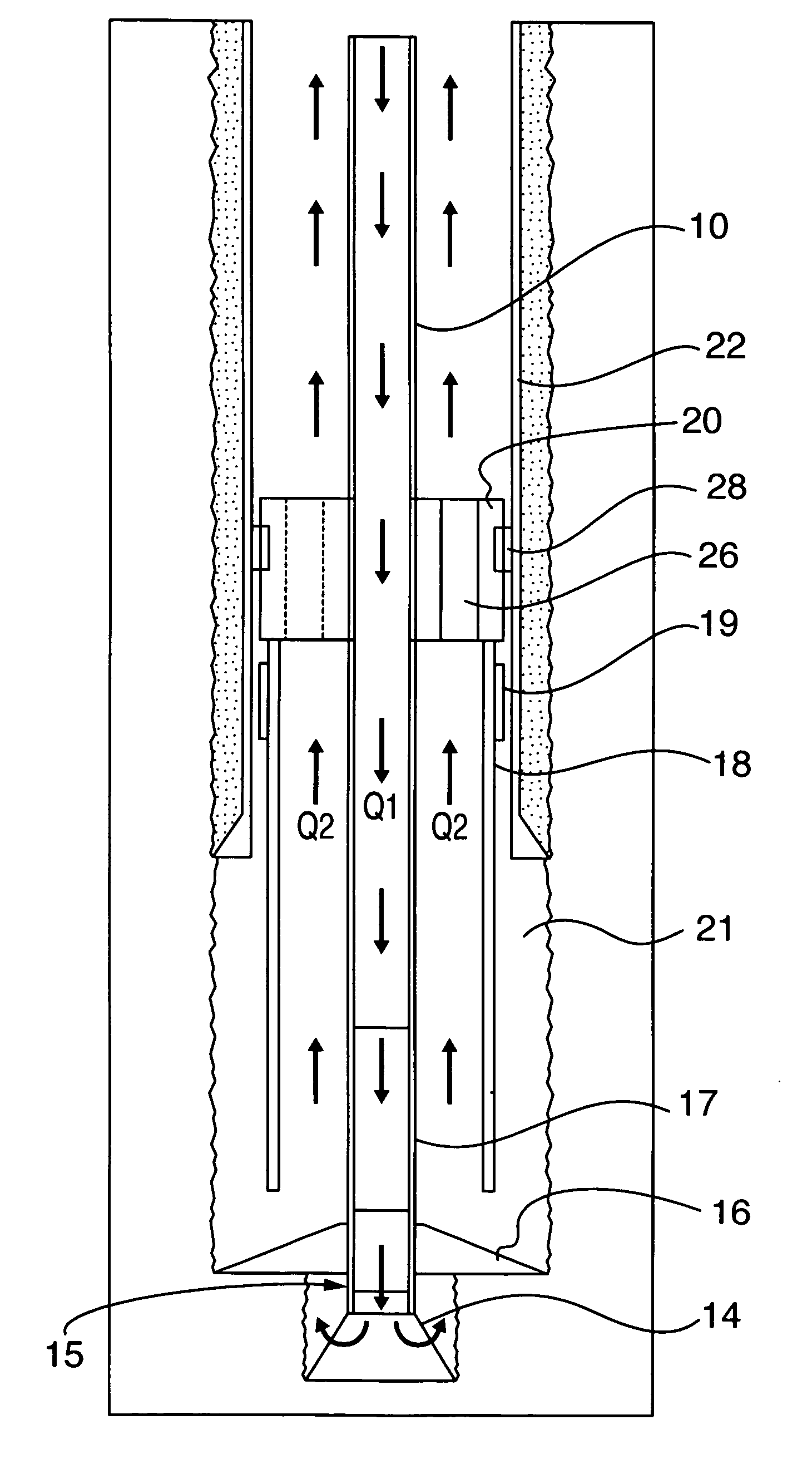
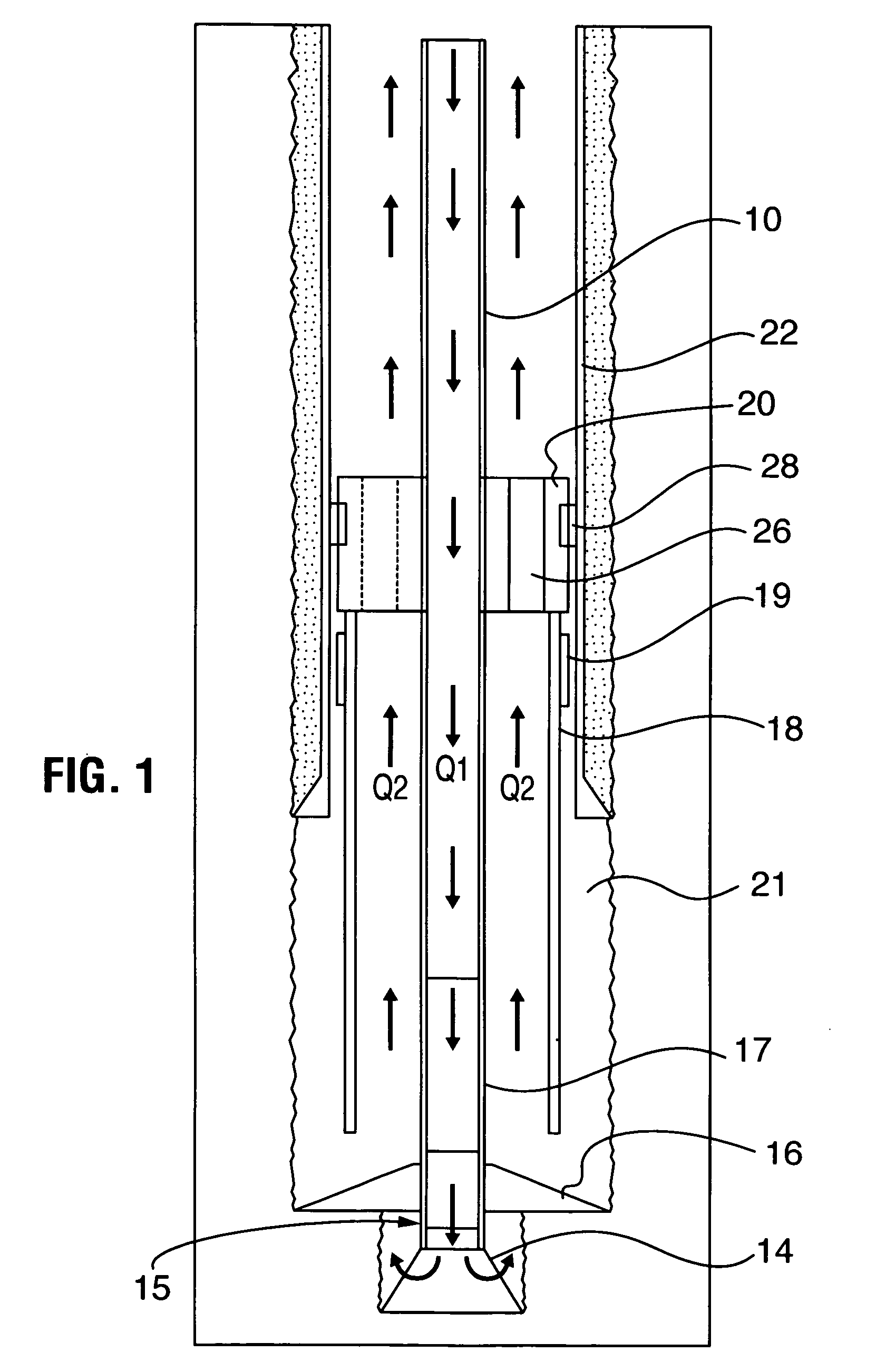
[0023]Drilling with a liner can be accomplished by drilling the liner in place using a drill string 10 formed of, for example, drill pipe or coiled tubing. Drill string 10 may extend from surface to the bottom 12 of the hole. Drill string 10 includes a center bore 13 and can include a bottom hole assembly 17 and a bit assembly 15 for drilling a borehole sized to accommodate passage therethrough of the liner. Drilling assembly 15 may include, for example, a pilot bit 14 and an underreamer 16 (as shown), a bicenter bit, a pilot bit and cutting shoe, etc. As will be appreciated, the bit assembly may be driven by various means such as for example a mud motor in the bottom hole assembly. A liner 18 may be hung onto drill string 10 by a ported sub 20. Ported sub 20 may be mounted on the drill string, for example about a drill string tubular member or the drill string can be connected thereto, as by threaded connection. Ported sub 20 may include a liner engaging surface for releasably enga...


PUM


Abstract

A method for drilling a borehole includes; providing a drill string of drill pipe including a center bore, a distal end, a bit assembly at the distal end; hanging a liner from the drill string, thereby forming an annular space between the drill string and the liner and with the bit assembly extending from a lower end of the liner; positioning the drill string with the liner attached thereto in a borehole such that a second annular space is formed between the liner and the borehole wall; operating the bit assembly to proceed with drilling the borehole; and circulating drilling fluid down through the center bore of the drill string out through the bit assembly and down through the second annular space between the liner and the borehole wall, the drilling fluid returning up through the annular space between the drill string and the liner.

Description

FIELD OF THE INVENTION[0001]The invention relates to drilling well bores and in particular a method and an apparatus for drilling a wellbore using a borehole liner.BACKGROUND OF THE INVENTION[0002]A drilling liner can be carried along behind the pilot bit to line a borehole while it is being drilled. Previously drilling fluid has been circulated down through a drill pipe, through the pilot bit and up the outer annulus between the drilling liner and the borehole wall. In these previous methods, drilling with a liner was often difficult. Pressure exerted on the formation due to a combination of the fluid density and the frictional pressure losses in the small annulus between the liner and the borehole / casing wall may induce fractures in the formation and cause lost circulation.[0003]Alternately, in other methods, the drilling fluid is circulated down through the drill pipe and forced up through the liner by sealing between the liner shoe and the borehole wall. This requires the use of...

Claims


Application Information

Patent Timeline
Patent Type & Authority Patents(United States)
IPC IPC(8): E21B7/26E21B7/20E21B21/10E21B33/14E21B43/10
CPCE21B7/20E21B43/10E21B33/14E21B21/103
Inventor TESSARI, ROBERT M.HOUTCHENS, BRUCE D.
Owner TESCO CORPORATION
Why Eureka
Try Eureka