Method and apparatus for depositing snow-ice treatment liquid on pavement

a technology of snow-ice treatment liquid and pavement, which is applied in the direction of snow cleaning, roads, roads, etc., can solve the problems of increasing the center of gravity of the truck, affecting the safety of drivers, so as to achieve the effect of minimizing air turbulen

Inactive Publication Date: 2006-09-19
KIME JAMES A
View PDF10 Cites 25 Cited by
  • Summary
  • Abstract
  • Description
  • Claims
  • Application Information

AI Technical Summary

Benefits of technology

[0017]The present invention is addressed to apparatus and method for treating a roadway or roadway by accurately depositing a volumetric quantity of snow-ice treatment liquid onto its surface with minimization of splash and overspray phenomena. With the method, the treatment liquid is expressed rearwardly from one or more streamer nozzles in correspondence with the forward velocity of the treatment vehicle. This control arrangement effects a substantially zero relative velocity between the expressed volume of liquid and the treated pavement surface. Disruption of the rearwardly expressed liquid by vehicle created air turbulence is minimized by aligning the axis of each streamer nozzle to be substantially in parallel relationship with the pavement surface as well as vehicle direction of movement and locating each nozzle in spaced adjacency with the pavement surface, for instance, about six inches or less. Such closely adjacent spacing further will take advantage of any surface effect between the expressed liquid volume and the pavement surface.
[0018]The accuracy of deposition of target liquid volumes per unit roadway distance is enhanced through the utilization of controlled fixed displacement pumps in conjunction with computed streamer nozzle effective diameters.
[0019]In a preferred embodiment particularly suited for pre-treating dry pavement prior to a weather event, three streamer nozzles are utilized including a left nozzle mounted laterally outwardly from the treatment vehicles' left wheel assembly; a right nozzle mounted laterally outwardly from the treatment vehicles' right wheel assembly and an intermediate nozzle located between the left and right wheel assemblies. One of the left or right nozzles is operator activated to deposit treatment liquid at the higher elevation or crown region of a roadway lane, while the intermediate nozzle is utilized in concert with the elected right or left nozzle. With this arrangement, the pretreatment liquid is deposited at regions which are not located within the wheel tracks of normal coincident traffic. Thus, the treatment liquid may dry upon the pavement without disruption from such coincident vehicular traffic. On the occasion of a weather event, the liquid weather precipitation then reconstitutes the deposited and dried brine as a liquid which then migrates, as it were, downhill into the wheel tracks of vehicular traffic to prevent the formation of a snow-ice-pavement bond. Such pretreatment substantially facilitates subsequent plow based removal of snow and ice.

Problems solved by technology

Thus, when into a given run, the dump bed will be elevated, dangerously raising the center of gravity of the truck under inclement driving conditions.
Without a disruption of that bond, little improvement to roadway traction will be achieved.
For example, the plow merely will scrape off the snow and ice to the extent possible, only to leave a slippery coating which may be more dangerous to the motorist than the pre-plowed road condition.
When salt has been simply broadcast over an ice laden pavement from a typical spinner, it will have failed to form a brine of sufficient salt concentration to break the ice-pavement bond.
The result usually is an ice coated pavement, in turn, coated with a highly dilute brine solution developed by too little salt, which will have melted an insufficient amount of ice for traction purposes.
In general, an adequate salt concentration using conventional dispersion methods requires the distribution of unacceptable quantities of salt on the pavement.
A result has been that the thus-deposited brine concentration essentially immediately dilutes to ineffectiveness at the ice surface, with a resultant dangerous liquid-coated ice roadway condition.
Attempting to remove ice from pavement by dissolving the entire amount present over the entire expanse of pavement to be treated is considered not to be acceptable from an economical standpoint.
The problem of excessive salt requirements remains, however, as well as difficulties in mixing a highly corrosive brine with particulate salt.
However, as the brine passes through the granular salt material, it dissolves the granular salt such that the salt will not remain in solution and will recrystallize, causing bridging phenomena and the like inhibiting its movement into a distribution auger.
Above those slow speeds, the material essentially is lost to the roadside.
Observation of materials attempted to be deposited at higher speeds shows the granular material bouncing forwardly, upwardly, and being broadcast over the pavement sides such that deposition at higher speeds is ineffective as well as dangerous and potentially damaging to approaching vehicles.
However, the broadcasting trucks themselves constitute a serious hazard when traveling, for example at 15 mph, particularly on dry pavement, which simultaneously is accommodating vehicles traveling, for example at 65 mph.
The danger so posed has been considered to preclude the highly desirable procedure of depositing the salt material on dry pavement just before the onslaught of snow / ice conditions.
Of course, operating at such higher speeds with elevated dump truck beds also poses a hazardous situation.
In addition to the hazards posed by slow speeds of travel, trucks utilized for snow-ice treatment exhibit difficulties negotiating ice coated roadways, particularly where uphill grades are encountered.
This procedure achieves only marginal traction and is manifestly an undesirable solution to this traction problem.
Notwithstanding the excellent physical results achieved with pre-treatment or “anti-icing” roadway brining, the problems associated with deposition on high speed interstate roadway systems have continued.
When the brine is applied from downwardly angulated spray bars at the rear of trucks at speeds above about thirty miles per hour, significant amounts of the brine are lost, due, for example, to turbulence behind the application truck.
Compounding this deposition problem is the generation of turbulence derived brine overspray, splashed or mist which will extend about one hundred feet behind a truck traveling at about fifty miles per hour.

Method used


Image

  • Method and apparatus for depositing snow-ice treatment liquid on pavement
  • Method and apparatus for depositing snow-ice treatment liquid on pavement
  • Method and apparatus for depositing snow-ice treatment liquid on pavement

Examples


Embodiment Construction

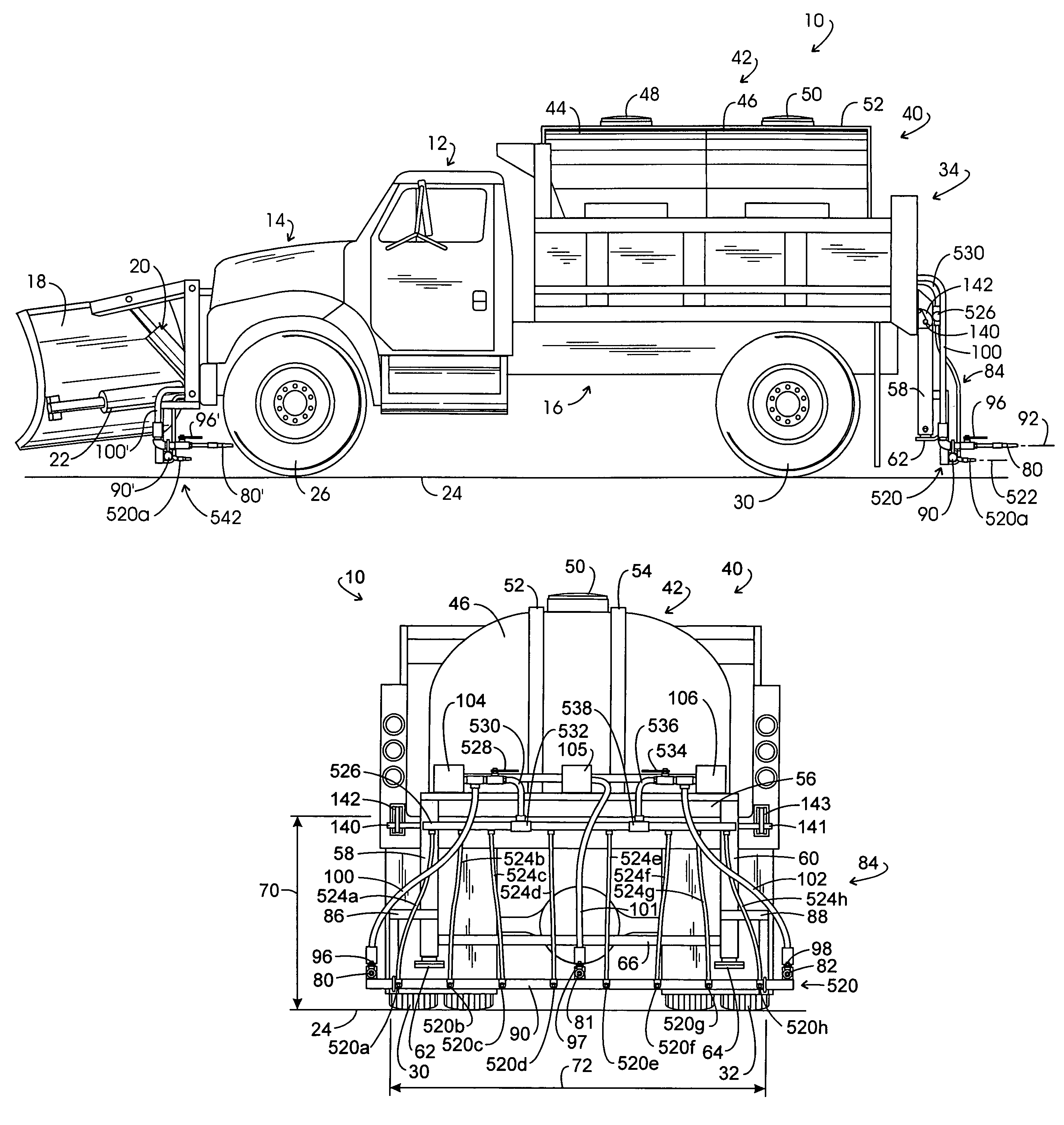
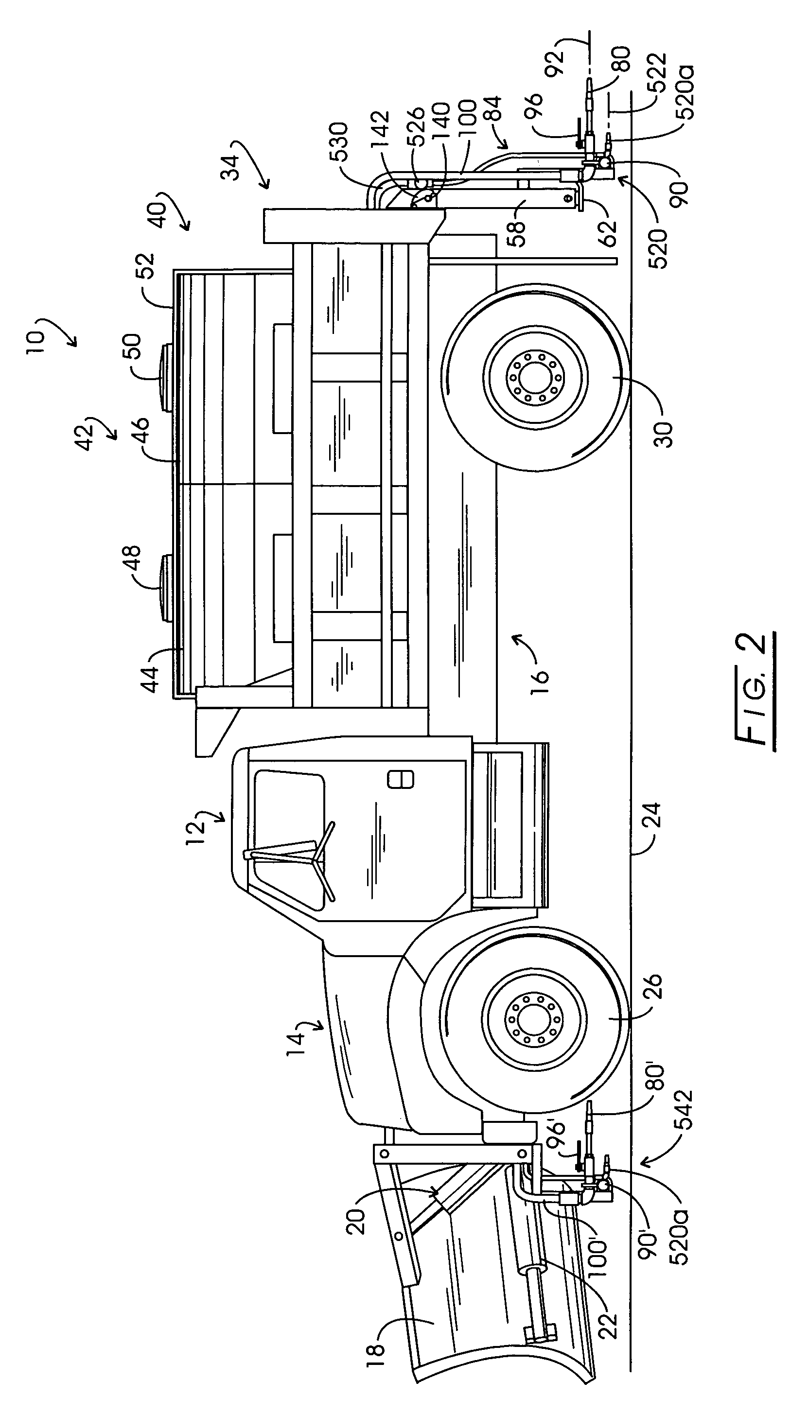
[0036]In the discourse to follow two, alternate approaches for accurately dispensing snow-ice control liquid at high speeds on primary roadway pavement are disclosed. It may be recalled that for pretreatment or anti-icing procedures, this deposition of the snow-ice control liquid is made on dry pavement before precipitation weather occurs. With each approach, the liquid brine is expressed from one or more streamer nozzles, the axes of which are substantially parallel to the roadway surface, at a volumetric flow rate which corresponds with the forward velocity of the dispensing vehicle. Thus, a substantially zero relative velocity is extant between what may be considered a horizontal column of liquid and the roadway surface. These streamer nozzles also are mounted such that they are in a relatively close spaced adjacency with the roadway surface such that the liquid stream being ejected tends to avoid air turbulence caused by the traveling dispensing vehicle and takes advantage of an...


PUM


Abstract

Method and apparatus for depositing liquid brine on roadway surface. Substantially horizontally disposed streamer nozzles are employed in conjunction with brine pumps which are operated in correspondence with the forward speed of the treatment vehicle. Substantially horizontally disposed streamer nozzles express the fluid at a rate corresponding with the vehicle forward velocity to effect a relative zero velocity relationship between the pavement and liquid. These streamer nozzles are mounted close to the pavement surface at a location effective to avoid truck induced air turbulence.

Description

CROSS-REFERENCE TO RELATED APPLICATIONSSTATEMENT REGARDING FEDERALLY SPONSORED RESEARCH[0001]Not applicable.BACKGROUND OF THE INVENTION[0002]Roadway snow and ice control typically is carried out by governmental authorities with the use of dump trucks which are seasonally modified by the addition of snow-ice treatment components. These components will include the forwardly-mounted plows and rearwardly-mounted mechanisms for broadcasting materials such as salt or salt-aggregate mixtures. The classic configuration for the latter broadcasting mechanisms included a feed auger extending along the back edge of the dump bed of the truck. This hydraulically driven auger effects a metered movement of material from the bed of the truck onto a rotating spreader disk or “spinner” which functions to broadcast the salt across the pavement being treated. To maneuver the salt-based material into the auger, the dump bed of the truck is progressively elevated as the truck moves along the roadway to be...

Claims


Application Information

Patent Timeline
Patent Type & Authority Patents(United States)
IPC IPC(8): A01G25/09B05B1/20B05D1/00E01H10/00
CPCE01H10/007
Inventor KIME, JAMES A.
Owner KIME JAMES A
Why Eureka
Try Eureka