Packaging and applicator device for a cosmetic product and/or a beauty care product incorporating a means of heating

a cosmetic product and heating device technology, applied in the direction of heating elements, heating furnaces, packaged goods, etc., can solve the problems of uneven deposition of make-up, deterioration of cosmetic properties of products, etc., and achieve the effect of reducing aging or potential deterioration, reducing the aging or the aging of cosmetic products

Inactive Publication Date: 2006-09-19
LOREAL SA
View PDF6 Cites 39 Cited by
  • Summary
  • Abstract
  • Description
  • Claims
  • Application Information

AI Technical Summary

Benefits of technology

[0008]The object of the invention is to simplify the actions entailed in applying make-up, while at the same time limiting or reducing the aging or potential deterioration of a cosmetic product held in a container in a quantity such that it can be used for numerous or plural successive applications. The device acco

Problems solved by technology

This technique poses a problem associated with premature aging of the product not being used for a given application, and when this product is used in subsequent applications, it will have been re-heated numerous times. Aging can cause deterioration of the cosmetic properties of the product, for example, volatilization of the

Method used


Image

  • Packaging and applicator device for a cosmetic product and/or a beauty care product incorporating a means of heating
  • Packaging and applicator device for a cosmetic product and/or a beauty care product incorporating a means of heating
  • Packaging and applicator device for a cosmetic product and/or a beauty care product incorporating a means of heating

Examples


first embodiment

[0053] illustrated in FIG. 4, the heat-dissipating layer forms a tube 33 made of a conducting material. This tube 33 is connected to the tracks 28 and 29 and is incorporated into the thickness of the insulating support 31. Preferably, the thickness 34 of the insulation 31 on the side facing the channel 32 is small in order to achieve better heat diffusion. This type of heating means 12 is obtained, for example, by bi-injection.

second embodiment

[0054] illustrated in FIG. 5, the heated wall 17 is formed from a metallic (or other electrically conductive material) helical structure 35 over-molded with the insulating material of the support 31. In the illustrated arrangement, the axis of the helix 35 is superimposed on the axis of the channel 32. The metallic structure 35 is connected to the tracks 28 and 29.

third embodiment

[0055]In a third embodiment illustrated in FIG. 6, the heated wall 17 is formed from a metallic helical structure 36 sheathed with insulating material 37 and held in a groove 38 formed in the inner circumference of the support 31. The helix can therefore be assembled last into the groove 38 or after the supported is formed.

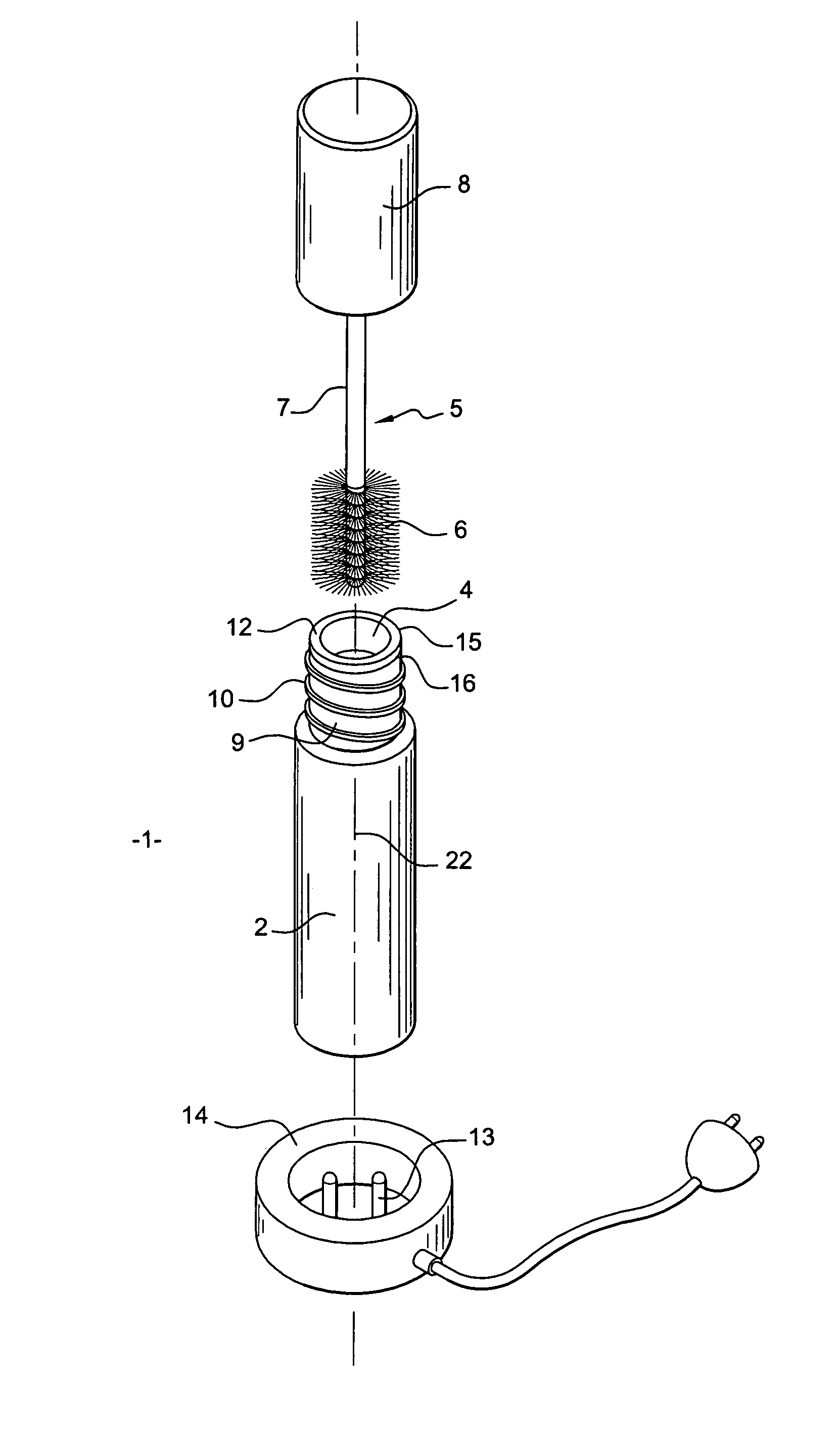
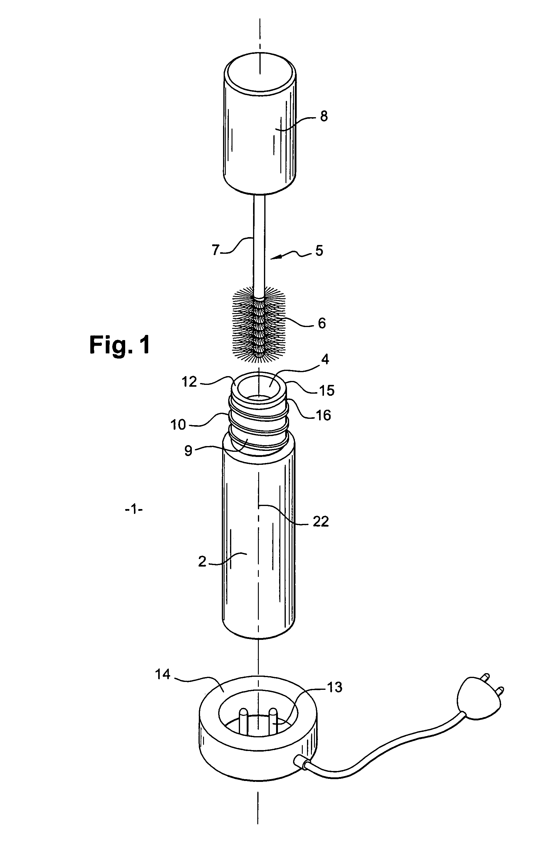
[0056]Preferably, the heating means 12 also performs a stripping function at the level of the outlet opening 4. The shape of the support 31 is adapted to perform this stripping function. The support 31 is generally a component fitted to the body of the reservoir 2. For this purpose, by way of example, in the illustrated arrangement the support 31 presents on its outer circumference means 39 facilitating attachment on the reservoir 2. These means 39 are, for example, bosses designed to press against an inner wall of the neck 9. The support 31 is, for example, fitted after the reservoir 2 has been filled with the product 3.

[0057]To perform the stripping function, th...


PUM


Abstract

A packaging and applicator device for a formulation used, for example, for make-up and/or care of keratinic fibers. The device includes a reservoir in which the formulation is placed, and an applicator capable of being loaded with a quantity of the formulation. The reservoir includes a heating device capable of heating at least a portion of the applicator and the quantity of product with which it is loaded when the device is not in a closed position of the reservoir. Heating is preferably permitted when the applicator is in an intermediate position, held at the level of an opening in the reservoir, with the circumference of this opening having at least one heated wall. The heated wall preferably incorporates a stripper element mounted in the reservoir opening.

Description

CROSS REFERENCE TO RELATED APPLICATIONS[0001]This document claims priority to French Application Number 03 03578, filed Mar. 24, 2003 and U.S. Provisional Application No. 60 / 462,711, filed Apr. 15, 2003, the entire contents of which are hereby incorporated by reference.FIELD OF THE INVENTION[0002]The invention relates to a packaging and applicator device for a cosmetic product and / or a beauty care product incorporating a heating device.BACKGROUND OF THE INVENTIONDiscussion of Background[0003]U.S. Pat. No. 5,856,653 describes a heating container that includes a recess which can accommodate a tube containing a cosmetic product. The container is arranged so as to impart a slow heating action by transference of the heat emitted by the container through the walls of the tube to the cosmetic product contained therein. The container can be used to heat and possibly re-fluidize residues of product that have dried on the tube walls, thereby rendering them re-usable for a fresh application of...

Claims


Application Information

Patent Timeline
IPC IPC(8): A46B11/08A45D34/04A45D33/26A45D34/00A45D40/00A45D40/18A45D40/26A46B9/02A46B11/00B05C17/00B65D51/32B65D83/00H05B3/42
CPCA45D40/265H05B3/42A46B9/021A46B11/08B65D51/32A45D33/26A45D40/18A45D40/267A45D2040/0006A45D2200/155A46B11/0006A46B2200/1046A46B2200/1053A45D2200/157
Inventor FONTAINE, MICHEL
Owner LOREAL SA
Why Eureka
Try Eureka