Catheter

a catheter and catheter tip technology, applied in the field of catheters, can solve the problems of port occlusion, build-up of fibrin on the catheter tip, damage to the vein lining, etc., and achieve the effect of reducing the exit flow velocity of venous blood

Inactive Publication Date: 2006-09-19
RADIUS INT PARTNERSHIP
View PDF51 Cites 87 Cited by
  • Summary
  • Abstract
  • Description
  • Claims
  • Application Information

AI Technical Summary

Benefits of technology

[0017]Still another object is to provide a dual lumen catheter which is capable of returning processed blood to the patient at high flow rates without harmful firehosing of the catheter tip.
[0042]In the second form of bolus the venous port is also modified. The bolus is formed so that the venous passage adjacent this port not only enlarges to a circular cross-section form as it approaches the port but curves toward the bolus axis. This results in a reduction in exit flow velocity of venous blood. The bolus wall at the trailing edge of the venous port is relatively thicker as a consequence of this venous passage curvature and less likely to abrade.

Problems solved by technology

However, problems occur with both the line introducing purified blood back into the vein (the venous or outflow line) and the line removing blood for purification (the arterial or intake line) at flow rates above 300 ml per minute.
A high flow rate from the venous line may cause whipping or “firehosing” of the tip in the vein with consequent damage to the vein lining.
A corresponding high flow rate into the arterial line may cause the port to be sucked into the vein wall, resulting in occlusion.
Thus, “firehosing” frequently results.
Fire-hosing may damage the vein wall, triggering the build-up of fibrin on the catheter tip.
Fibrin build-up may result in port occlusion.
However, such catheters have not been entirely successful in solving problems related to hemodialysis with dual lumen catheters, e.g., high incidences of catheter port occlusion as well as some degree of fire-hosing.
Pliability can create a problem during insertion, however, because the catheters can kink when they meet resistance.
These catheters are more likely to cause damage to body tissue during insertion than bullet nose catheters, for example, because of their flat ends and side edges.
Open ended catheters are also more likely to damage tissue than bullet nose catheters while in-situ.
Nevertheless, the need for deep catheter insertion has heretofore made guide wire insertion of open-ended catheters an accepted procedure in spite of the disadvantage of their flat or blunt end design.
This approach has generally been found undesirable, however, because the hole in the bullet nose can later collect particulate matter and be a focal point for infection.

Method used


Image

  • Catheter
  • Catheter
  • Catheter

Examples


Embodiment Construction

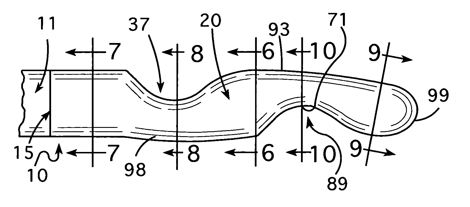
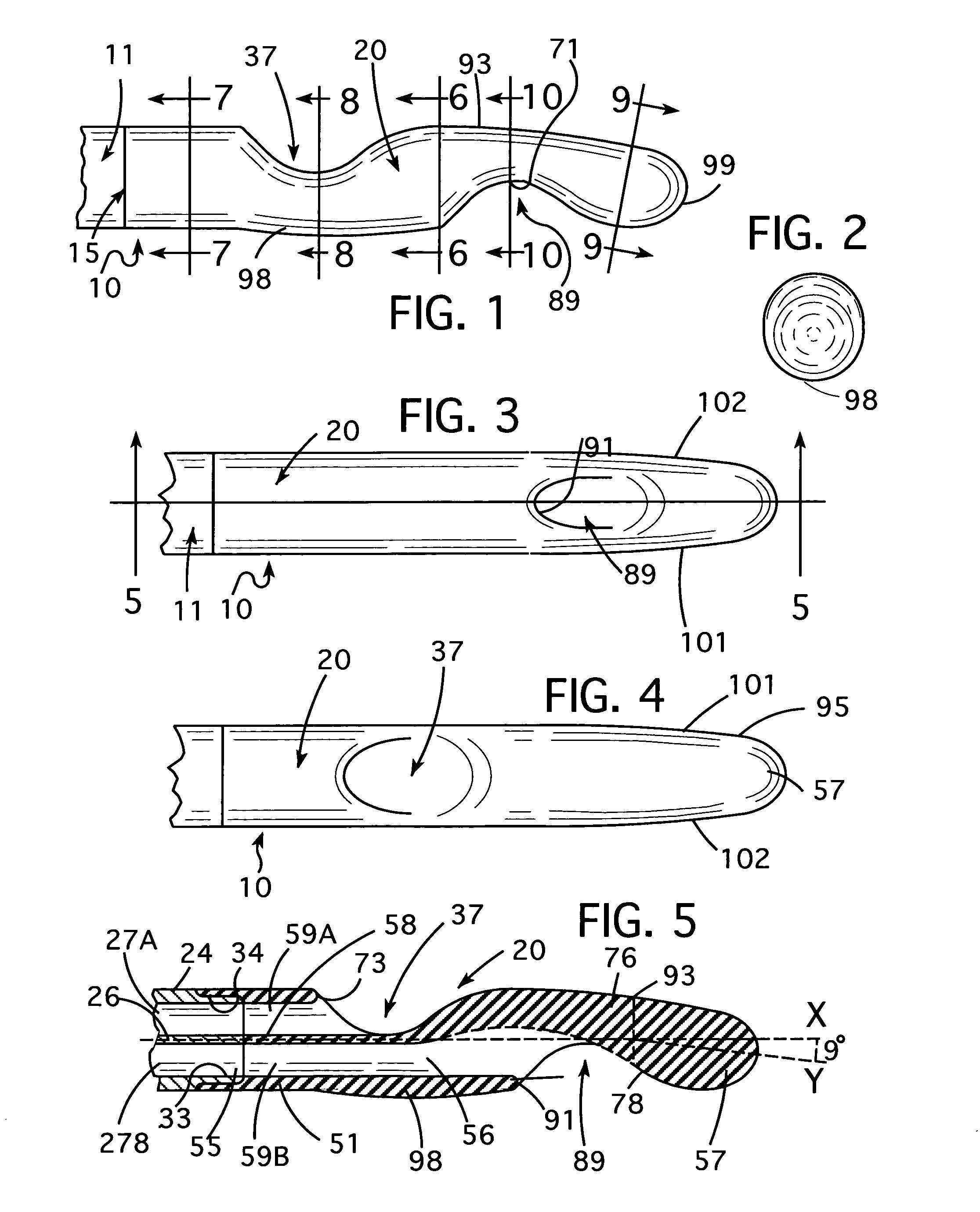
[0074]Referring now to the drawings and particularly to FIGS. 1–10, a dual lumen catheter embodying features of a first form of the invention is illustrated generally at 10. The catheter 10 comprises a cylindrical tube 11 (only partially shown) having a distal end 15. A bolus 20 is attached to the distal end 15 of the tube 11.

[0075]The tube 11 illustrated is a standard 14.5 French tube formed of a plastic material such silicone or polyurethane. In this embodiment the tube 11 shown is formed of MED-4700 silicone and is manufactured by NuSil Technologies. The tube 11 is formed by extruding a tubular body 24 with a generally cylindrical wall 25 and a septum 26. The 14.5 French tube 11 has an O.D. of 0.192 inches.

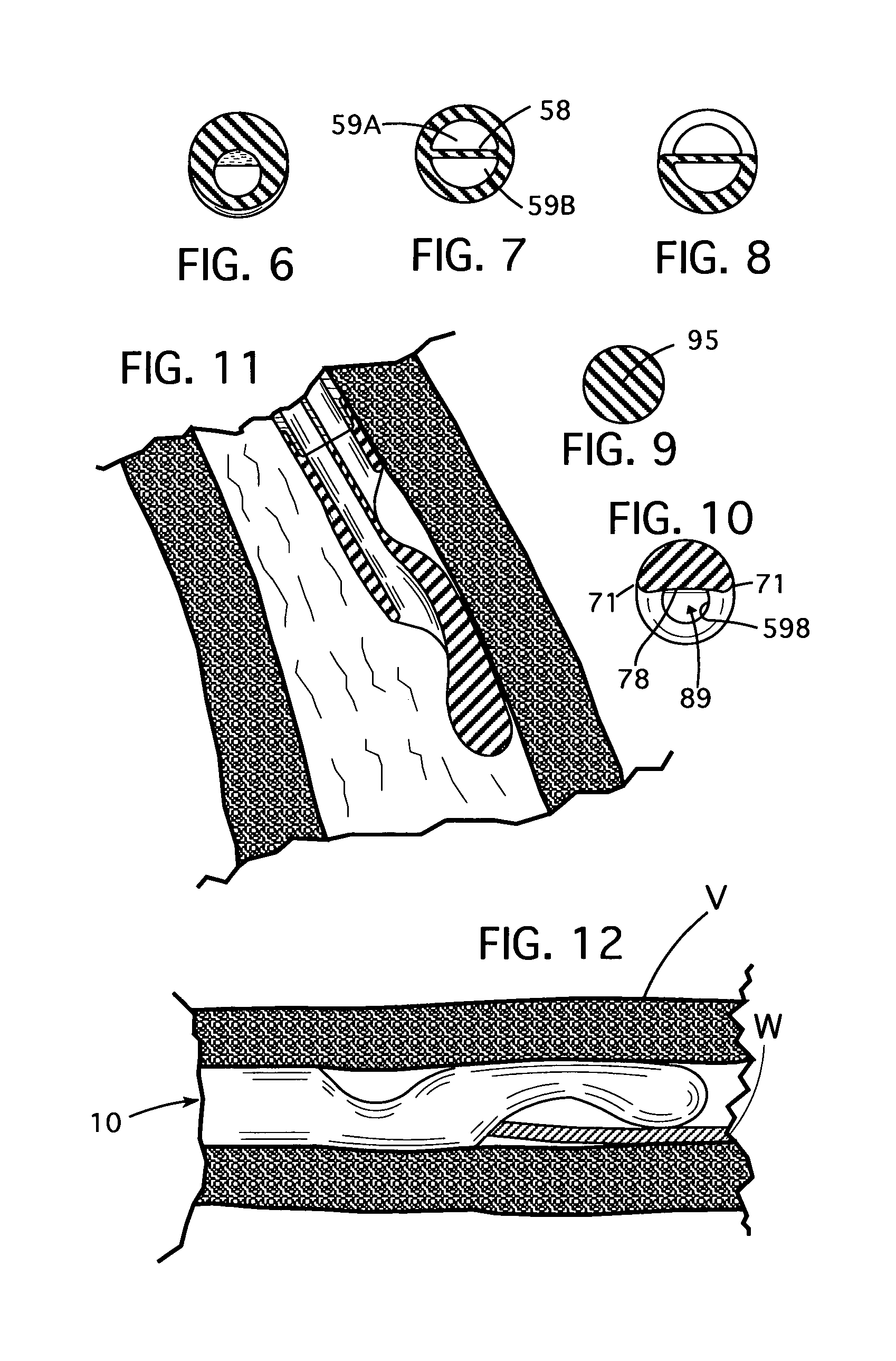
[0076]The tube body 24 is divided by the septum 26 into two identical D-shape lumens 27A and 27B extending through the tube body along its length. The lumen 27A is normally an arterial lumen and the lumen 27B is normally a venous lumen. Each lumen 27A and 27B has a D-shape cros...


PUM


Abstract

A catheter comprising a dual lumen tube with a bolus at its distal end having a bullet nose. A venous port is formed in one side of the bolus adjacent the bullet nose of the bolus. An arterial port is formed in the bolus circumferentially displaced 180° around the catheter from the venous port. The bolus contains a venous passage which transitions from a smaller two-thirds moon shaped cross-section to a larger circular cross-section. The arterial passage has a crescent-moon shaped cross-section. The bullet nose is not as thick as the tube and is inclined on an angle to the axis of the tube so that a portion of its outer periphery is substantially tangent to a hypothetical cylinder containing the trailing edge of the venous port.

Description

RELATED APPLICATIONS[0001]This application is a continuation-in-part of U.S. application Ser. No. 09 / 853,511 filed May 11, 2001 now U.S. Pat. No. 6,461,321, which claims the benefit of provisional U.S. Application Ser. No. 60 / 266,617, filed Feb. 6, 2001. Application Ser. No. 09 / 853,511 is a continuation-in-part of U.S. application Ser. No. 09 / 759,582, filed Jan. 11, 2001 now U.S. Pat. No. 6,702,776, which is a continuation-in-part of PCT application Ser. No. PCT / US00 / 32000 designating the United States filed Nov. 21, 2000. PCT application Ser. No. PCT / US00 / 32000 designating the United States is, in turn, a continuation-in-part of U.S. application Ser. No. 09 / 651,763 filed Aug. 30, 2000 now U.S. Pat. No. 6,517,529.FIELD OF THE INVENTION[0002]This invention relates in general to catheters. It relates specifically to catheters for use in blood vessels. Hemodialysis catheters, employ the invention to particular advantage.BACKGROUND OF THE INVENTION[0003]Catheters are inserted in the vas...

Claims


Application Information

Patent Timeline
Patent Type & Authority Patents(United States)
IPC IPC(8): A61M3/00A61M1/00A61M1/36A61M25/00
CPCA61M1/3653A61M25/003A61M25/0068A61M1/3661A61M25/007A61M25/0069A61M1/0084A61M25/0032A61M25/008A61M2025/0031A61M2025/0037A61M2025/0081A61M1/3659A61M1/85
Inventor QUINN, DAVID G.
Owner RADIUS INT PARTNERSHIP
Why Eureka
Try Eureka