Wound therapy and tissue management system and method with fluid differentiation

a tissue management system and wound technology, applied in the field of medical care, can solve the problems of tissue breakdown and necrosis, bacterial overgrowth, and ineffective current tissue management and fluid drainage procedures,

Inactive Publication Date: 2006-09-19
KCI LICENSING INC
View PDF80 Cites 598 Cited by
  • Summary
  • Abstract
  • Description
  • Claims
  • Application Information

AI Technical Summary

Problems solved by technology

However, current tissue management and fluid drainage procedures are often ineffective in maintaining optimum moisture content for promoting wound healing.
Excessive drying, on the other hand, can lead to desiccation, eschar formation and slowing of cell migration.
Excessive moisture, on the other hand, can lead to maceration, bacterial overgrowth, tissue breakdown and necrosis.
A disadvantage with many conventional dressings is that they require changing in order to reduce the risk of infection and to maintain effectiveness.
However, dressing changes can add significantly to treatment costs and are associated with patient discomfort and medical risks such as infection and damage to reepithelialized tissues.
Sufficient moisture levels are required for epithelial cell migration, but excessive moisture can inhibit drying and maturation of the epithelial layer.
Heretofore, there has not been available a system or methodology that allowed the manipulation of multiple mechanical forces affecting wound surfaces.
Moreover, there has not previously been available a system or methodology that manipulated the gradients of gases, solids, liquids and medications in such a way as to provide the medical practitioner with various options for delivering various agents either systemically from the patient side or topically from the external side of a wound.
Still further, there has not been available a wound treatment system and methodology utilizing a transfer element for the manipulation of gas and liquid pathways under the control of preprogrammed, coordinated influx and efflux cycles.

Method used


Image

  • Wound therapy and tissue management system and method with fluid differentiation
  • Wound therapy and tissue management system and method with fluid differentiation
  • Wound therapy and tissue management system and method with fluid differentiation

Examples


first modified embodiment

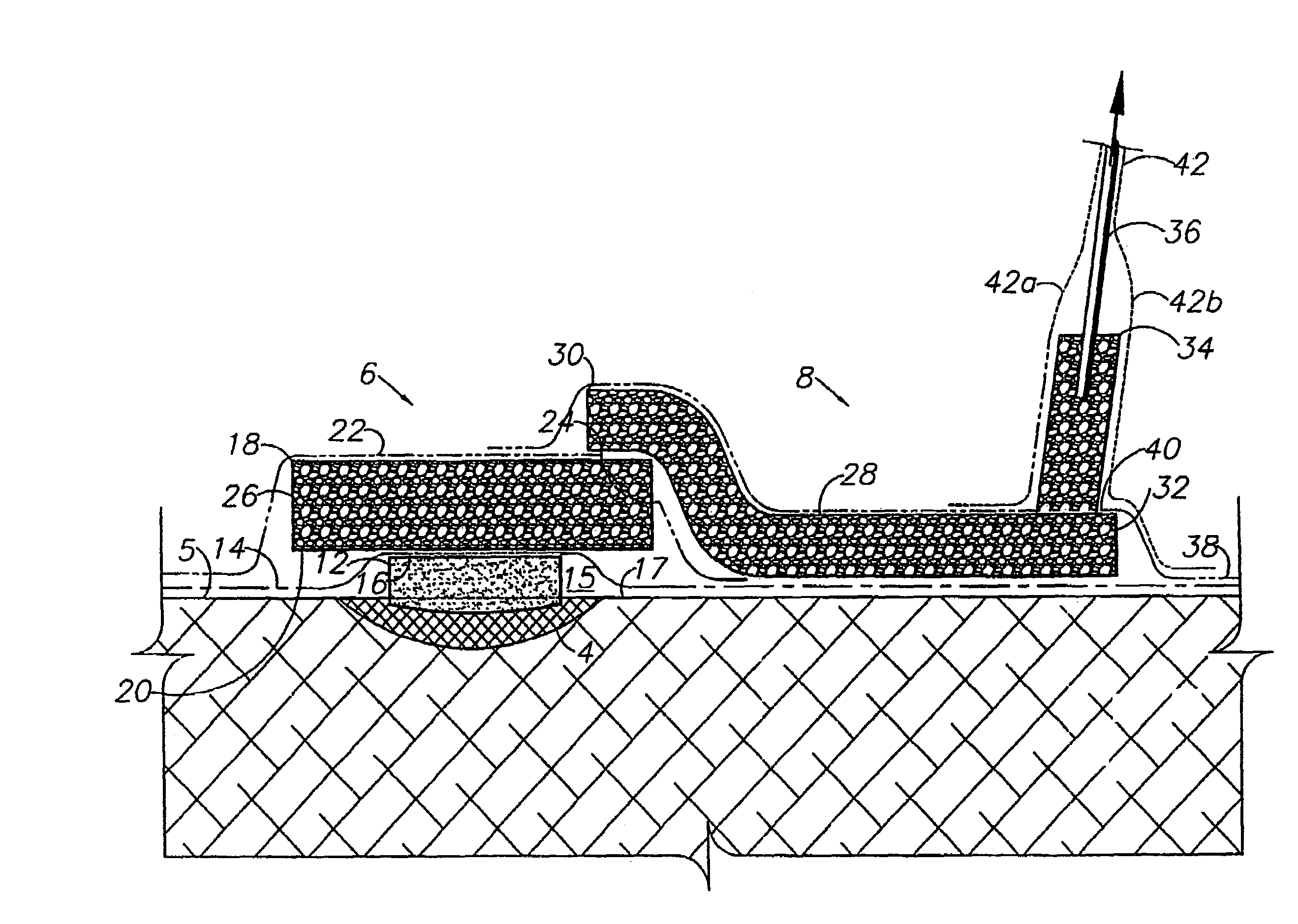
III. First Modified Embodiment Fluid Differentiating Wound Dressing 53

[0048]A wound dressing 53 comprising a first modified embodiment of the present invention is shown in FIG. 4 and includes a liner 54 between the wound 4 and a first sponge 56, which can comprise a hydrophilic or hydrophobic material. The liner 54 passes fluid, but partially isolates and shields the wound tissue from the first sponge 56 to prevent the formation of spicules penetrating the open-passage first sponge 56. The liner 54 thus permits the first sponge 56 to comprise hydrophobic (e.g., PUE) material, even when spicule penetration is not desired.

second modified embodiment

IV. Second Modified Embodiment Fluid Differentiating Wound Dressing 102

[0049]A wound dressing comprising a second modified embodiment of the present invention is shown in FIG. 5 and generally comprises a collector assembly 106 and a transfer assembly 108. The collector assembly 106 can be similar to the collector assembly 6 with a suitable composite construction. The transfer assembly 108 comprises an elbow connector 110 placed on top of a second sponge drape 112 covering the second sponge 114. The elbow connector 110 mounts the distal end 116 of a suction tube 118, which is also connected to a vacuum source 10. A first sponge drape 120 is placed over a first, hydrophilic sponge 122 and includes a central opening 123 communicating with the second sponge 114.

[0050]FIG. 5a shows an interface device 102a comprising a variation of the construction of the wound dressing 102. The device 102a utilizes a flexible, bellows-type tubing section 110a in place of the elbow connector 110 describe...

third modified embodiment

V. Third Modified Embodiment Fluid Differentiating Wound Dressing 202

[0051]A fluid differentiating wound dressing 202 comprising a third modified embodiment of the present invention is shown in FIGS. 6–8 and generally comprises a transfer assembly 204 (FIG. 6) adapted for mounting on a collector assembly 206 as shown in FIG. 7.

[0052]The transfer assembly 204 comprises a sponge material buffer 208 which can comprise, for example, polyurethane ether (PUE). The buffer 208 is encased in first and second drape panels 210, 212 with wings 210a, 212a respectively extending in opposite directions from the buffer 208. The wings 210a, 212a have an adhesive layer 214, which is covered by a removable backing sheet 216 prior to installation. Tab strips 218 are provided at the ends of the drape wings 210a, 212a. The tab strips 218 are attached by perforated lines 220 for easy removal upon installation. The suction tube 36 is embedded in the buffer 8 and extends outwardly from the transfer assembly...


PUM


Abstract

A wound therapy and tissue management system utilizes fluid differentiation. Fluid is differentiated by establishing a gradient within the system. A gradient can be established with matter or energy. Patient interfaces for establishing, maintaining and varying one or more gradients include transfer elements with first and second zones having different flow coefficients. The transfer elements exchange fluid with a patient, generally through a wound site, and with external components of the system. Osmotic solution gradients are controlled by a methodology involving the present invention for extracting solutions, which can include toxins, from patients and for introducing fluids and sumping air to wound sites.

Description

CROSS-REFERENCE TO RELATED APPLICATION AND PRIORITY CLAIM[0001]The present application is based on and claims priority in U.S. Provisional Patent Application Ser. No. 60 / 287,323; filed Apr. 30, 2001.BACKGROUND OF THE INVENTION[0002]1. Field of the Invention[0003]The present invention relates generally to medical care, and in particular to wound therapy and tissue management systems and methodologies with fluid differentiation.[0004]2. Description of the Prior Art[0005]Heretofore, many wound therapy and tissue management devices and protocols have tended to focus on the addition or control of individual mechanical forces and their respective effects on wound healing. For example, the use of suction to secure skin graft dressings in place in disclosed in Johnson, F. E., An Improved Technique for Skin Graft Placement Using a Suction Drain; Surgery, Gynecology and Obstetrics 1984; 159 (6): 584–5. Other prior art devices have focused on the application of compressive (i.e. positive or gr...

Claims


Application Information

Patent Timeline
Patent Type & Authority Patents(United States)
IPC IPC(8): A61F13/00A61F13/02A61M1/00A61M27/00A61M35/00
CPCA61M1/0058A61M27/00A61M1/0088A61F7/02A61F2007/0059A61M2205/3368A61M35/00A61M1/915A61M1/94A61M1/77
Inventor ZAMIEROWSKI, DAVID S.
Owner KCI LICENSING INC
Why Eureka
Try Eureka