Expandable intraluminal endoprosthesis

a technology of endoprosthesis and expandable parts, which is applied in the field of expandable intraluminal endoprosthesis, can solve the problems of reduced and even poor stent-to-vessel ratio at these locations, and high rigidity of stent segments in their crimping and deployed state, so as to improve the mechanical bond and improve the behaviour of this part, the effect of improving flexibility

Inactive Publication Date: 2006-09-19
ORBUSNEICH MEDICAL PTE LTD
View PDF23 Cites 101 Cited by
  • Summary
  • Abstract
  • Description
  • Claims
  • Application Information

AI Technical Summary

Benefits of technology

[0008]It is an aim of the present invention to provide a balloon expandable stent which combines a high degree of uniformity and flexibility with excellent design capabilities.
[0028]Once deployed, the structure will orient itself in line with the helical lattice structure which it forms, exhibiting three intertwining continuous lattice legs within the intermediate region and only two of those legs in the central region. The intermediate region will possess more stiffness in order to counteract the balloon expansion, known as the “dog bone effect”, which causes the ends of the device to flare prematurely prior to the deployment of the central section and which results in an undue amount of foreshortening upon expansion. Moreover the intermediate regions serve as a relief between the end portions and the central region of the device.

Problems solved by technology

Their drawback is that the physician needs to place the right device and thereby has to rely on information derived from fluoro and angiographic equipment.
Although this stent is most widely used and tested in practice, it has been implanted in over 600000 patients all over the world, it still suffers from a number of drawbacks.
The main drawbacks have to do with the stent-to-vessel-ratio uniformity and crimped as well as deployed flexibility.
However, due to the inevitable bridges between adjacent tubes of the Palmaz-Schatz™ stent, there will be a bare area between adjacent segments of the stent once it has been deployed giving rise to a decreased and even poor stent-to-vessel-ratio at these locations.
The other drawback concerns the rather high rigidness of the stent segments in their crimped and deployed state.
As a consequence the stent has only a limited flexibility which hinders the delivery of the stent to its intended position inside the body.
The poor deployed flexibility of this stent gives rise to a straightening of the vessel over segments longer than typically 2 cm which appears to be a primary cause for late term restenosis of the stented area.
However, because of its constitution this device offers only a poor design freedom when it conies to tailoring the design to add specific functionality and remove certain drawbacks.
Also the internal stress in the device once it has been wound hinders the provision of reliable welds between adjacent turns.
These welds as well as those to the ends of the wire moreover remain a weak point especially during expansion of the device.

Method used


Image

  • Expandable intraluminal endoprosthesis
  • Expandable intraluminal endoprosthesis
  • Expandable intraluminal endoprosthesis

Examples


first embodiment

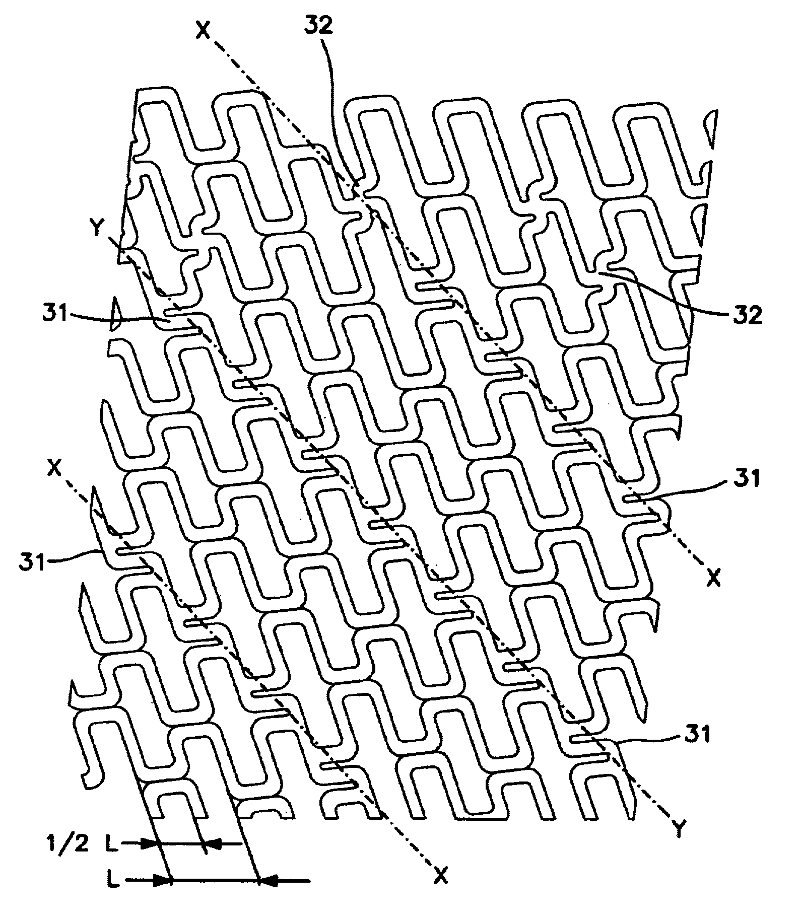
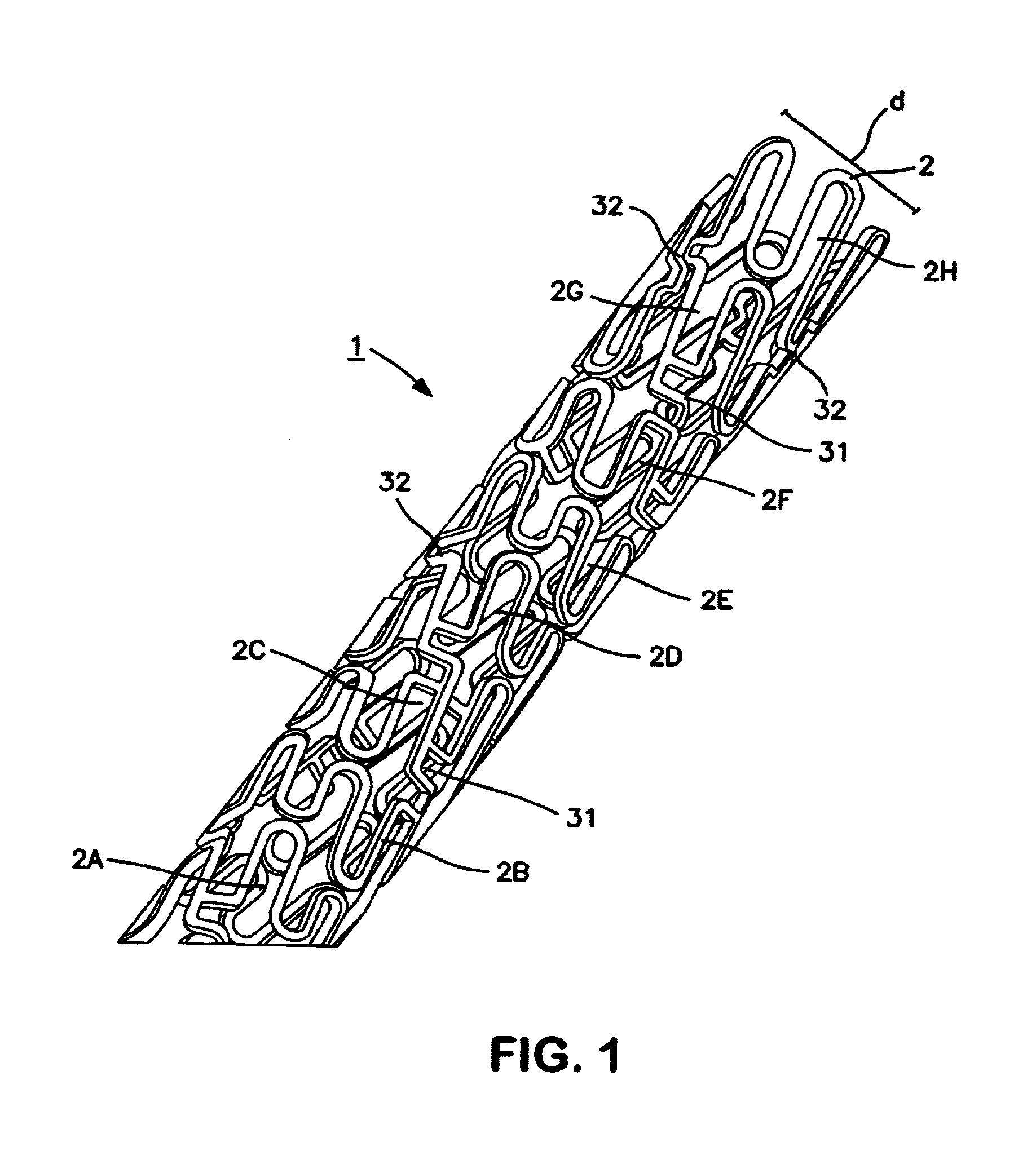
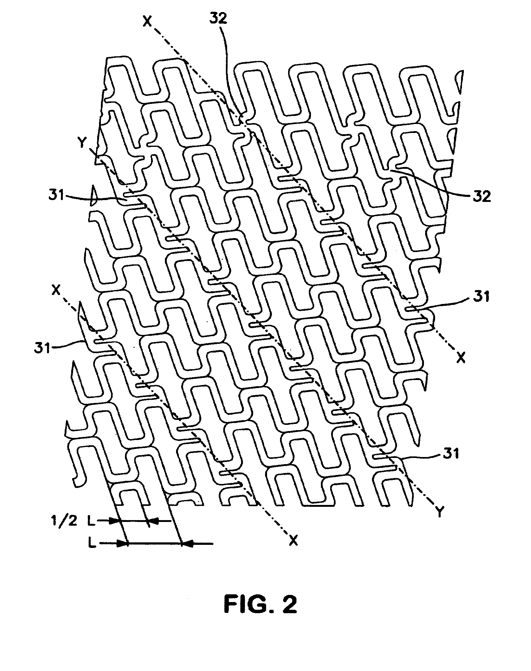
[0047]Different to the structure of the first embodiment, connection elements 33 to subsequent turns of said pattern are shifted by about a full pitch distance. As a result a full undulation 25 will link said connection elements 33 to one another and as such creates an elongated member 25 in between the connection elements 33. Said elongated member formed by an intermediate undulation comprises a S-curved bent and is longer than the linear distance between the interconnection elements thereby linked to each other, at least in the crimped state shown in FIGS. 5 and 6. This imparts additional slack and considerable expandability to the spinal ladders which are formed by such a series of linked connection elements in the deployed state shown in FIG. 7. Moreover the orientation of the S-curved bents in said elongated members 25, which is substantially parallel to the longitudinal axis of the body at least in the crimped state shown in FIGS. 5 and 6, allows the member 25 to uniformly exp...

second embodiment

[0051]Also the elongated members interlinking a series of connections elements like in the second embodiment need not coincide with undulations of the pattern and can be introduced in the structure as separate elements. These members moreover need not necessarily comprise a full S-curved bent or even any S-curved bent at all and may on the other hand consist of more than just one such bent. Also in this respect the designer has total freedom to tailor the device to his demands.


PUM


Abstract

An expandable intraluminal endoprosthesis including a tubular member (1) a first diameter which permits intraluminal delivery of the member into a lumen of a body passageway, particularly a blood vessel. The tubular member (1) is capable of acquiring a second, expanded and deformed diameter upon the application from the interior of the tubular member of a radially outwardly extending force, which second diameter is variable and dependent on the amount of the force applied to the tubular member. Such a tubular member may be expanded and deformed to expand the lumen of the body passageway. The wall of the tubular member includes a substantially continuous structure (2) of mutually staggered undulations. This structure has been separated from a tube wall and exhibits at least one pattern which advances substantially helically along a longitudinal axis of the tubular member. Connection elements within the structure connect adjacent undulations to each other. These connection elements are an integral extension of the undulations thereby interconnected.

Description

[0001]This application is a continuation of application Ser. No. 09 / 094,402 filed on Jun. 10, 1998 (now U.S. Pat. No. 6,117,165).[0002]The present invention relates to an expandable intraluminal endoprosthesis comprising a tubular member having a first and second end and a wall surface disposed between said first and second end, the wall having a substantially uniform thickness and having a first diameter in a first, unexpanded state which permits intraluminal delivery of the member into a lumen of a body passageway, particularly a blood vessel, which member is capable of acquiring a second diameter in an expanded and deformed state upon the application from the interior of the tubular member of a radially outwardly extending force, which second diameter is variable and dependent on the amount of said force applied to the tubular member, whereby the tubular member may be expanded and deformed to expand the lumen of the body passageway. More particularly the invention relates to an e...

Claims


Application Information

Patent Timeline
Patent Type & Authority Patents(United States)
IPC IPC(8): A61F2/06A61F2/84A61F2/90
CPCA61F2/91A61F2/915A61F2/88A61F2002/91508A61F2002/91516A61F2230/0013A61F2002/91533A61F2002/91541A61F2002/9155A61F2002/91558A61F2002/91583A61F2002/91525
Inventor BECKER, GARY J.
Owner ORBUSNEICH MEDICAL PTE LTD
Why Eureka
Try Eureka