Transient-phase PWM power supply and method

a power supply and transient phase technology, applied in the direction of power conversion systems, dc-dc conversion, instruments, etc., can solve the problems of low power dissipation in the drive transistor, inefficient operation, and significant power is typically dissipated across, so as to reduce or eliminate the effect of transients on the regulated supply

Inactive Publication Date: 2006-09-19
INTERSIL INC
View PDF14 Cites 44 Cited by
  • Summary
  • Abstract
  • Description
  • Claims
  • Application Information

AI Technical Summary

Benefits of technology

[0010]By providing such a regulator, transients on the regulated supply can be reduced or eliminated by engaging a faster drive ...

Problems solved by technology

In the past, linear power supplies have been used, but a significant amount of power is typically dissipated across the pass element.
Therefore, in the full-on mode, there is low power dissipation in the drive transistor even at a relatively high current.
Of course, without proper filtering, longer on times at relatively high currents will typically cause the drive transistors to rather quickly, overcharge the filter capacitor and, thus, drive the output voltage above the regulated range.
But as stated above, because these transistors have relatively slow on/off times, such operation would be very inefficient.
Although this allows the drive transistors to operate efficiently and to provide large amounts of power, the response time of each main phase to transients (caused by sudden demands for either an increase or a decrease in p...

Method used


Image

  • Transient-phase PWM power supply and method
  • Transient-phase PWM power supply and method
  • Transient-phase PWM power supply and method

Examples


Embodiment Construction

[0015]The following discussion is presented to enable a person skilled in the art to make and use the invention. The general principles described herein may be applied to embodiments and applications other than those detailed below without departing from the spirit and scope of the present invention. The present invention is not intended to be limited to the embodiments shown, but is to be accorded the widest scope consistent with the principles and features disclosed or suggested herein.

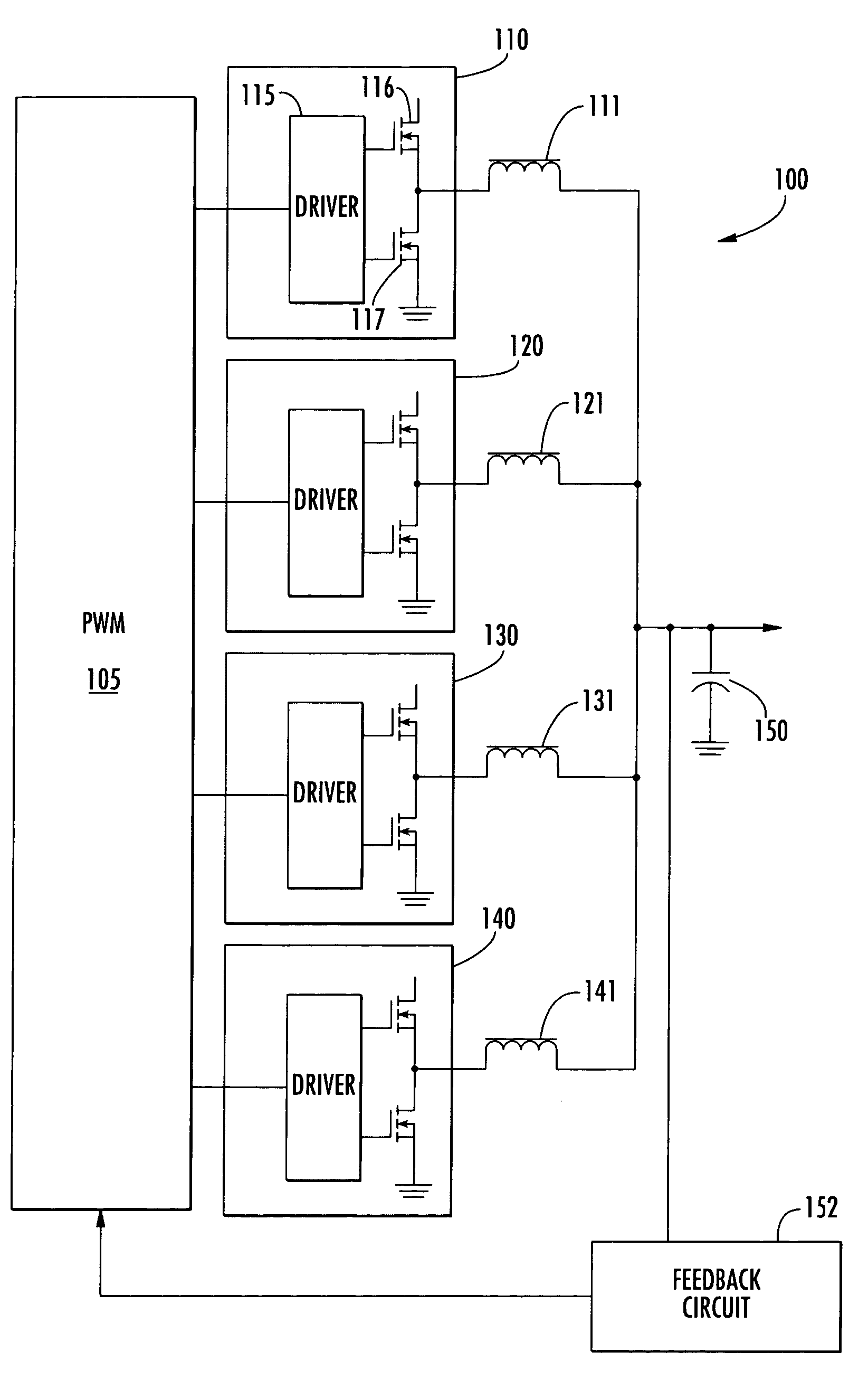
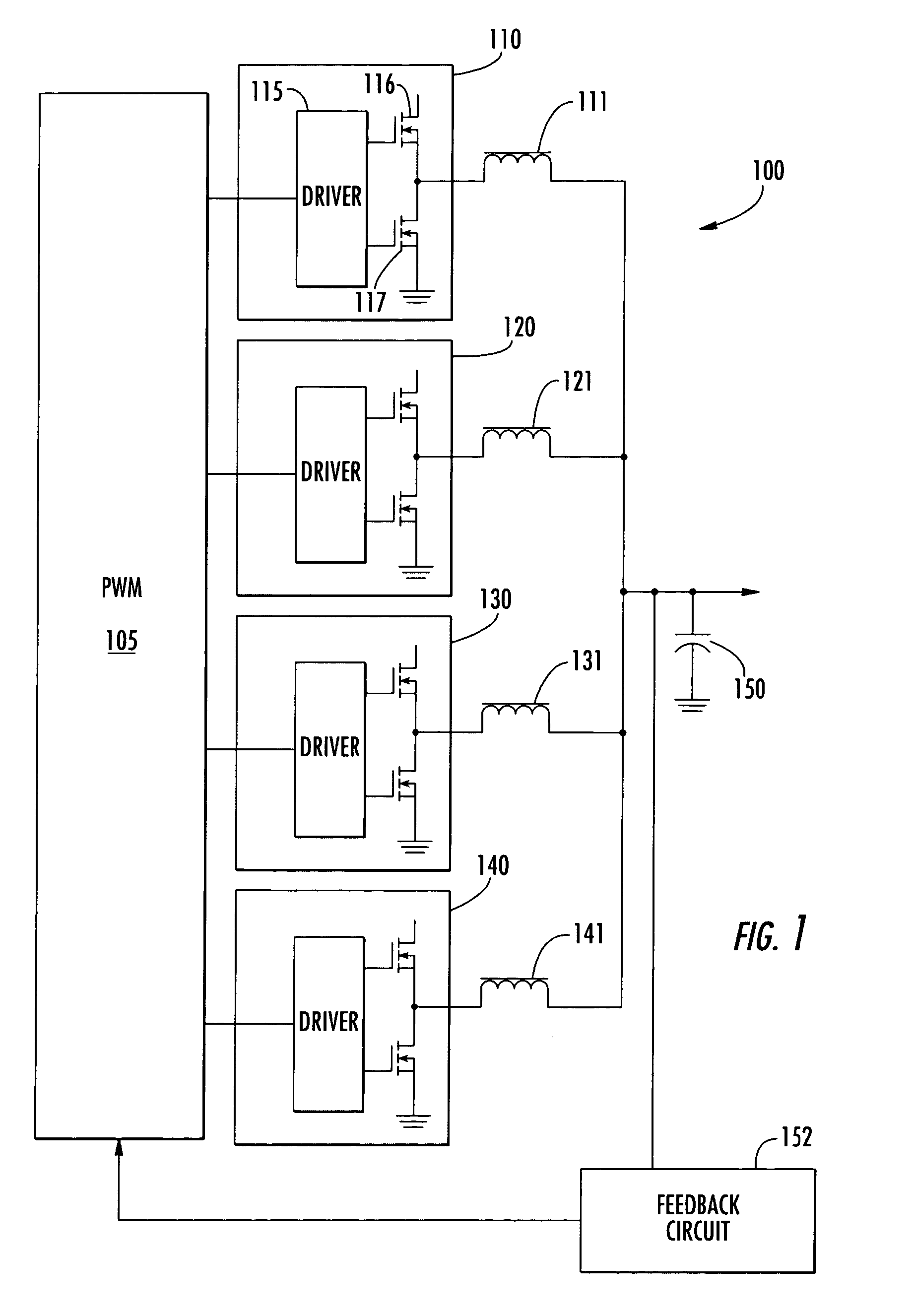
[0016]FIG. 1 shows a schematic diagram of a PWM power supply 100 in accordance with an embodiment of the invention. The PWM power supply 100 of FIG. 1 includes a pulse-width modulator 105, four drive circuits 110, 120, 130, and 140, along with corresponding filter inductors 111, 121, 131, and 141, a filter capacitor 150, and a feedback circuit 152. The drive circuits 110 and 120 represent two main phases and the drive circuits 130 and 140 represent two fast phases. The PWM power supply 100 is typica...


PUM


Abstract

A regulator supplies a regulated voltage to an electronic component with a plurality of phases with varying response rates. The regulator includes an output node that provides a regulated supply voltage, a first main-phase drive circuit that provides a first main load current to the output node and that has an on time and an off time, and a first transient-phase drive circuit that has a first transient load current to the output node that has an on time and an off time that are respectively less than the on and off times of the first main-phase drive circuit.

Description

CLAIM OF PRIORITY[0001]This application claims priority to U.S. Provisional Application Ser. No. 60 / 460,460, filed on Apr. 4, 2003, which is incorporated by reference.BACKGROUND OF THE INVENTION[0002]Today's electronic systems typically require a relatively high amount of current from one or more highly regulated power supplies. A typical computer system will draw 50–60 Amperes (A) (laptop) or 80–120 As (desktop / server) from a 1.2 to 1.3 volt (v) power supply. In the past, linear power supplies have been used, but a significant amount of power is typically dissipated across the pass element. As a result, pulse-width modulated (PWM) switching power supplies were introduced to provide power in a more efficient manner. Switching power supplies dissipate less power than linear power supplies because the drive transistors operate in either full-on or full-off mode. Specifically, in the full-on mode, the voltage drop across a drive transistor is minimal, and in the full-off mode, no curre...

Claims


Application Information

Patent Timeline
IPC IPC(8): G05F1/59H02M3/158
CPCH02M3/1584
Inventor SCHNEIDER, MICHAEL EDWIN
Owner INTERSIL INC
Why Eureka
Try Eureka