System and method for hydrocarbon reservoir monitoring using controlled-source electromagnetic fields

a technology of electromagnetic field and hydrocarbon reservoir, which is applied in the field of system and method for monitoring hydrocarbon reservoirs using controlled source electromagnetic field, can solve the problems of inability to provide a comprehensive image of reservoir geometry, inability to carry out continuous or repeated seismic surveying, and inability to extend monitoring applications. the effect of extending the monitoring application

Inactive Publication Date: 2006-09-19
RGT UNIV OF CALIFORNIA
View PDF21 Cites 70 Cited by
  • Summary
  • Abstract
  • Description
  • Claims
  • Application Information

AI Technical Summary

Benefits of technology

[0006]It is an advantage of the present invention to provide a method for the continuous or repeated mapping of reservoir structure over a large area without the use of expensive wells.
[0007]Another advantage of the present invention is to provide a method for generating a comprehensive image of reservoir geometry.
[0008]Still another advantage of the present invention is to provide an improved controlled electromagnetic transmitter for use in measurement and monitoring of sub-seafloor hydrocarbon reservoirs.
[0009]According to the present invention, time changes in the electrical resistivity of sub-seafloor hydrocarbon reservoirs are monitored using electromagnetic methods involving a controlled electromagnetic source. Changes in estimated reservoir resistivity occur when oil and gas are replaced by water. Both the thickness and lateral extent of the reservoir can be monitored by this method. Such monitoring allows well positions and extraction rates to be optimized for total extraction over the life of the reservoir.
[0010]In a first exemplary embodiment, a plurality of conductive cables, each connected to a plurality of receiver electrodes, are distributed over the seafloor around a hydrocarbon production platform so that they extend over the area of the hydrocarbon reservoir. An electromagnetic (EM) transmitter is positioned on the platform and is connected via a separate set of cables to one or more transmitting electrode pairs which are positioned at or near the seafloor. Where multiple electrode pairs are provided, electric currents can be applied either simultaneously or sequentially between pairs of transmitting electrodes, which are positioned to produce vertical, radial and / or azimuthal electric fields. The reservoir depth also governs the distances between transmitting and receiving electrodes, with a general rule that the distance should be at least three times the reservoir depth. Transmission frequencies are determined by the depth of the reservoir and the electrical conductivity of overlying sediments, and are typically 0.25 Hz for 1 km deep reservoirs. Transmission electrodes can be laid horizontally on the seafloor or hung vertically from the platform. Electric fields across the receiver electrodes which result from the EM transmissions are monitored on the production platform. Amplification of the signals from the receiver electrodes can be applied using sub-sea amplifiers or amplifiers located on the platform.
[0011]The size and position of the electric fields at the transmission frequencies determines the extent and thickness of the reservoir. The radial electric field mode is most sensitive to the reservoir lateral dimensions. By installing transmitter and receiver electrodes permanently on the seafloor, variations in the amplitude of the received EM signals depend only on changes in the reservoir, and not on relative proximity of other geology that would occur if the electrodes were to be moved.

Problems solved by technology

Seismic methods had traditionally been used for such purposes, however, the results could be ambiguous.
However, to date, applications of these methods to hydrocarbon reservoirs have been limited to identification and mapping of hydrocarbon-filled layers.
One existing technique involves the drilling of discrete monitoring wells, which, in addition to being expensive and time consuming, are incapable of providing a comprehensive image of reservoir geometry due to the small number of sampling locations.
In addition, due to the hazards to those who operate the air gun or are located nearby and the damage to or disturbance of marine life in a wide area around the pulses, continuous or repeated seismic surveying is both undesirable and impractical for extended monitoring applications.
Further, borehole seismic surveying involves expensive well down-time.

Method used


Image

  • System and method for hydrocarbon reservoir monitoring using controlled-source electromagnetic fields
  • System and method for hydrocarbon reservoir monitoring using controlled-source electromagnetic fields
  • System and method for hydrocarbon reservoir monitoring using controlled-source electromagnetic fields

Examples


third embodiment

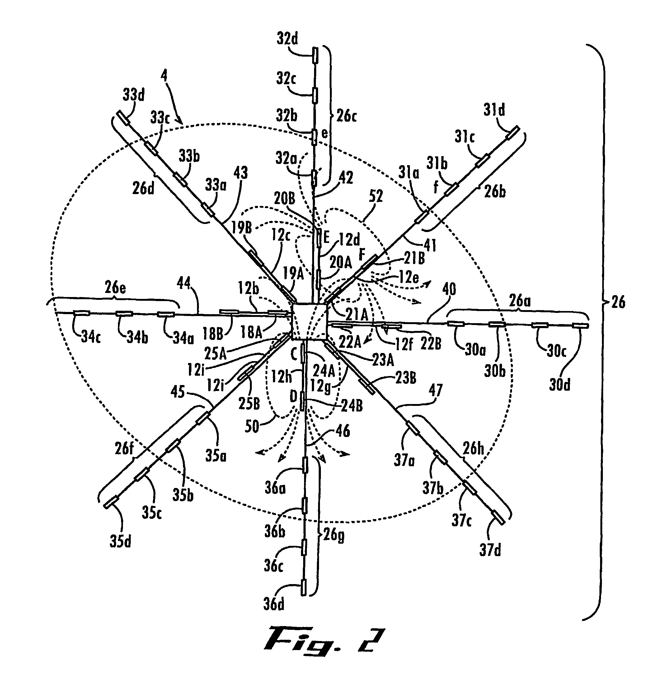
[0044]In the receiver configuration, permanent anchors can be installed at positions across the seafloor over the reservoir area, for example, in a configuration similar to that shown in FIG. 3. These permanent anchors are used to hold a plurality of removable receiver antennae in place. The receiver antennae can be repeatedly placed at the anchor sites using remotely-operated vehicles (ROVs), as are known in the art, just prior to placement of the towed transmitter into the water. Under this embodiment, no electronic equipment needs to be left at the site between measurement operations.

[0045]Selection of the optimum transmission frequency maximizes the ability to detect changes in the hydrocarbon reservoir thickness using the resistivity data obtained from electric fields remote from the transmitter. This optimum frequency is determined by the water depth, depth of the reservoir, electrical resistivity of the sediments over the reservoir, and the noise floor of the measuring system...

first embodiment

[0049]For a fixed installation transmission can be continuous, with a tradeoff between temporal resolution and noise floor. By stacking measurements over one day, a noise floor of 3×10⁻⁸ V / m / (Am) is obtained. This can be lowered to 1×10⁻¹⁸ V / m / (Am) with a one-week measurement. By summing measurements over one year, a noise floor of 10−19 V / m / (Am) can be approached. This probably represents the smallest measurement that can be made in practice.

second embodiment

[0050]For a repeat survey using deployed receivers and a ship-towed transmitter as in the second embodiment, bandwidths of a few minutes are possible before the transmitter location has changed significantly. Using 2 minutes and the above typical parameters, one gets a noise floor of 10−5 V / m / (Am).

[0051]FIG. 6b is a grayscale pixelplot illustrating sensitivity using the ratio of the horizontal, radial electric fields with the reservoir in the model shown in FIG. 6a to the electric fields for a fully depleted reservoir and the base model. The greyscale key to the right of the plot indicates the amplitude of the noise floor Nf.

[0052]The contour lines in FIG. 6b show the magnitude of the electric field with the reservoir present, in exponent form. That is, −20 is 10−20 V / m per dipole moment. First, one chooses a source-receiver range. This should be made as large as possible, but is limited by the reservoir size and the resolution desired. Here, 5 km (indicated by arrow “A”) is selecte...


PUM


Abstract

The system and method for real-time monitoring of a hydrocarbon reservoir (4) during extraction include an electro-magnetic source assembly (16) for transmitting a first plurality of electromagnetic fields. A plurality of seafloor antennae (30a–30d) is distributed over an area of the seafloor (8) corresponding to the reservoir (4), where each antenna (30a–30d) comprises recieves electrode array (30a–30d) adapted for receiving a second plurality of electromagnetic fields and generating signals corresponding to the detected fields. A data logging processor receives the signals over time and stores data corresponding to the signals. Different combinations of the receiver electrode are used in combination with transmitter antennae for measuring vertical, radial and / or azimuthal fields. Transmission and detection of the fields can be performed continuously or at timed intervals during hydrocarbon extraction to estimate the rate and efficiency of extraction.

Description

RELATED APPLICATIONS[0001]This application claims the priority of U.S. provisional application Ser. No. 60 / 432,467, filed Dec. 10, 2002, the disclosure of which is incorporated herein by reference in its entirety.FIELD OF INVENTION[0002]The present invention relates to measurement of the electrical conductivity at the seafloor in a controlled source electromagnetic survey for monitoring sub-seafloor hydrocarbon reservoirs and, more particularly, to a system and method for monitoring sub-seafloor hydrocarbon reservoirs during extraction.BACKGROUND OF THE INVENTION[0003]Measurement of electrical resistivity beneath the seafloor has assumed an important role in hydrocarbon, e.g., oil or natural gas, exploration and reservoir assessment and development. Seismic methods had traditionally been used for such purposes, however, the results could be ambiguous. Several electromagnetic methods have been developed for mapping sub-seafloor resistivity variations. See, for example, U.S. Pat. No. ...

Claims


Application Information

Patent Timeline
Patent Type & Authority Patents(United States)
IPC IPC(8): G01V3/12G01V3/15
CPCG01V3/12G01V3/083Y02A90/30
Inventor CONSTABLE, STEVEN C.
Owner RGT UNIV OF CALIFORNIA
Why Eureka
Try Eureka