

Soft-switching techniques for power inverter legs
a technology of inverter legs and soft switches, which is applied in the direction of electric variable regulation, process and machine control, instruments, etc., can solve the problems of inverter legs having a shoot-through or short-circuit situation, switching loss and stress, and switching transients or spikes, etc., and achieve the effect of lowering the minimum inverter frequency
- Summary
- Abstract
- Description
- Claims
- Application Information
AI Technical Summary
Benefits of technology
Problems solved by technology
Method used
Image

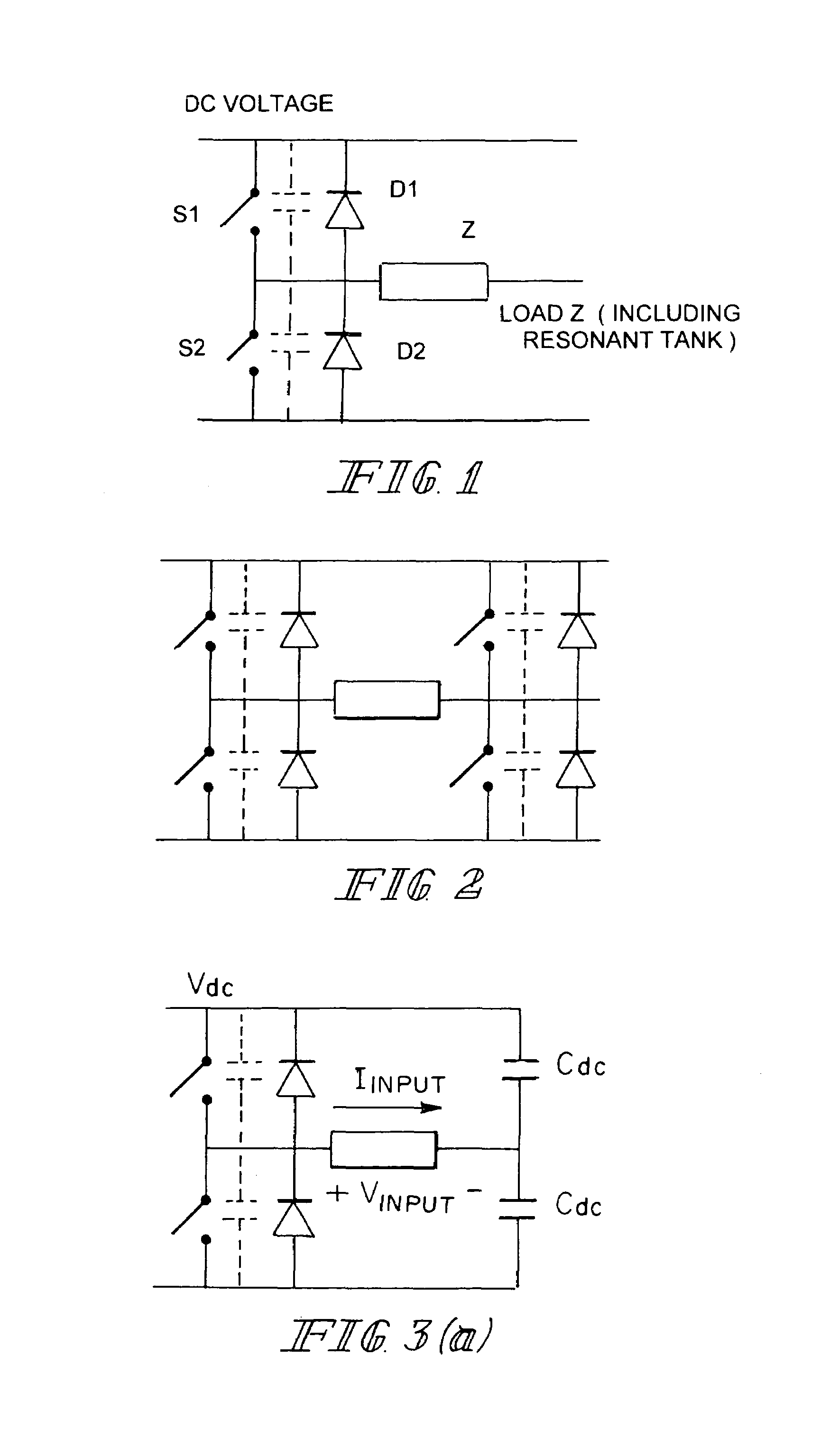
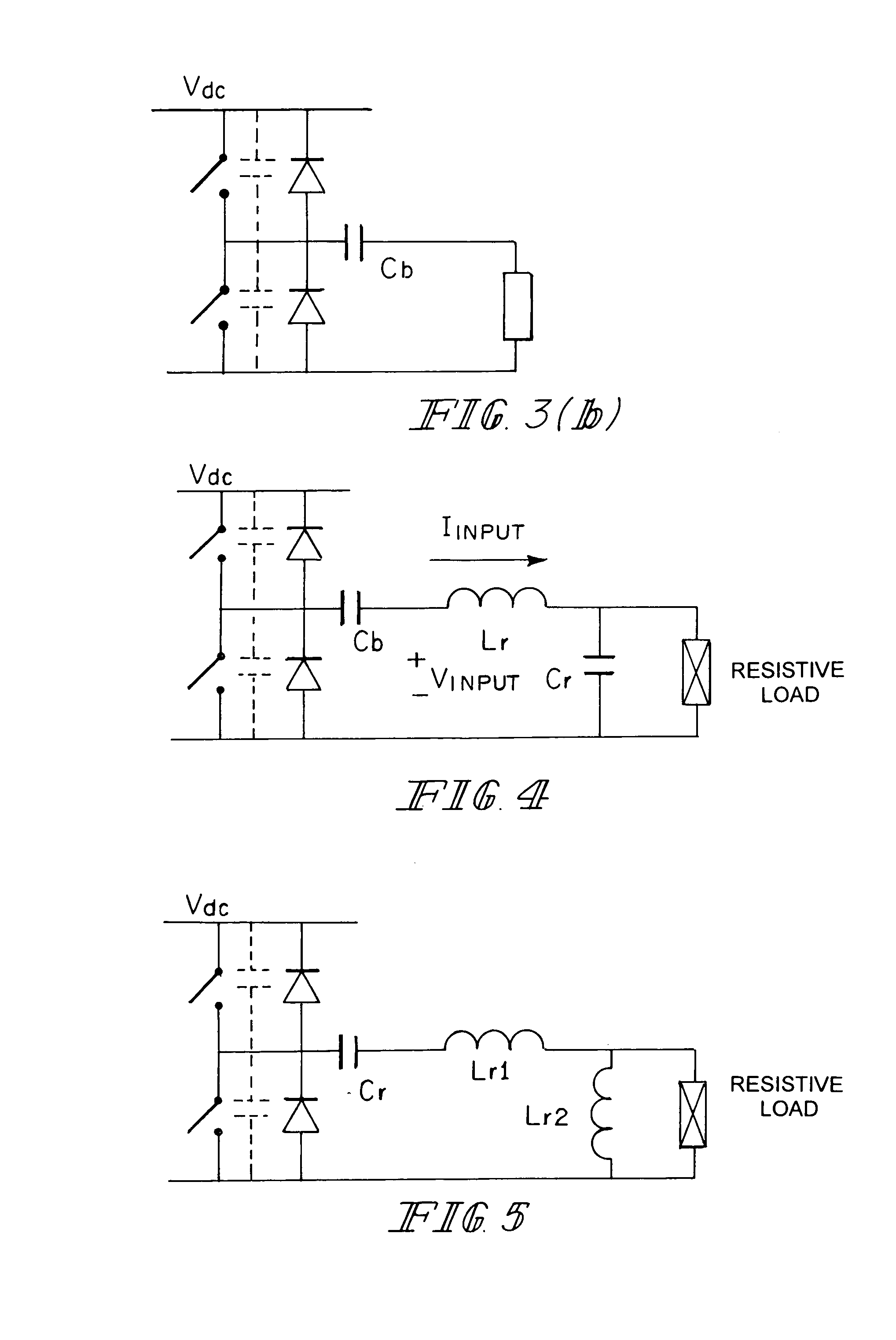
Examples
experimental verification
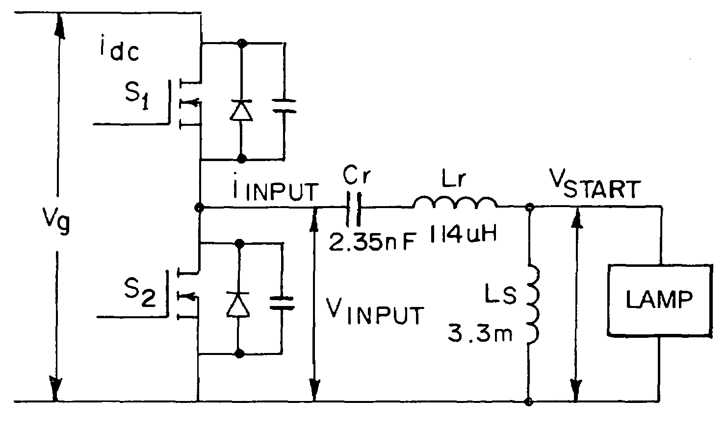
[0117]Test 5:
[0118]Simulated and experimental waveforms of Vinput and iinput were obtained from the circuit example under the following conditions are included.
[0119](i) Starting Inverter frequency fsL=64 kHz, with an open circuit load (representing a lamp before ignition).—FIG. 16.
[0120](ii) Starting Inverter frequency fsL=64 kHz, with a short circuit load (representing a lamp in the glow-to-arc transition).—FIG. 17.
[0121](iii) Steady-state inverter frequency fs=fsH=370 kHz (higher than frH=308 kHz and fa=280 kHz), with an open circuit load (representing a lamp arc extinction).—FIG. 18.
[0122](iv) Steady-state inverter frequency fs=fsH370 kHz (higher than frH=308 kHz and fa=280 kHz), with an short circuit load (representing short-circuit load condition).—FIG. 19.
[0123]All simulated and measured results confirm that soft switching can be achieved at the relatively low starting inverter frequency operation and the high inverter frequency operation under both open and short circuit con...
PUM
 Abstract
Description
Claims
Application Information