
Radiographic apparatus and method for switching a grid

a technology of radiographic apparatus and grid, applied in the field of radiographic technique, can solve the problems of complex mechanism, inability to obtain suitable relationships between image reception frequency and grid reciprocation period, and inability to achieve the effect of obtaining suitable relationships between image reception time and reciprocation speed,

Inactive Publication Date: 2006-09-19
CANON KK
View PDF10 Cites 78 Cited by
  • Summary
  • Abstract
  • Description
  • Claims
  • Application Information

AI Technical Summary

Benefits of technology

The present invention provides a radiographic apparatus and method that can set a grid in radiography or fluoroscopy and execute fluoroscopy or radiography of an object under optimum imaging conditions. The apparatus includes irradiation means, detection means, acquisition means, setting means, selection means, and grid stripe reduction means. The method includes an irradiation step, a detection step, an acquisition step, a setting step, a selection step, and a grid stripe reduction step. The technical effects of the invention include improved image quality, reduced radiation dose, and improved accuracy in positioning and targeting of the object being imaged.

Problems solved by technology

In this case, however, when the grid is reciprocated by using the elastic force of a spring, as in a conventional grid mechanism, the reciprocating motion of the grid gradually attenuates with time.
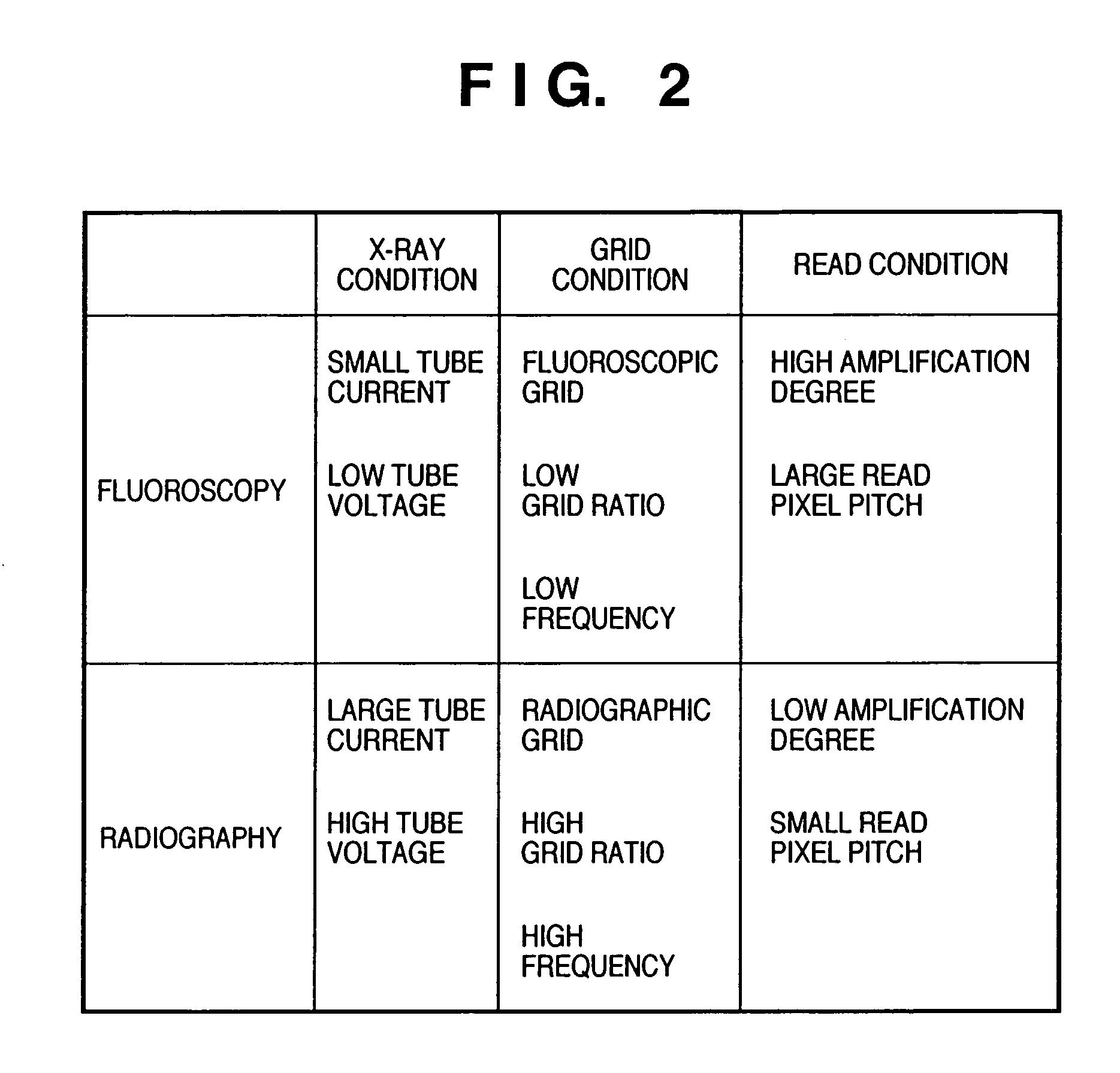
However, the radiographic apparatus which executes both fluoroscopy and radiography by using the FPD sensor using a semiconductor has the following problems.(1) The imaging dose in fluoroscopy is about 1 / 100 of that in radiography, which is, very small.(2) In addition to the X-ray dose, the tube voltage also changes between fluoroscopy and radiography.
Hence, the grid must appropriately be switched.(3) When a stationary grid is inserted, moiré is generated in the image depending on the grid frequency and the sampling pitch of the FPD sensor.(4) If the grid should be reciprocated, the mechanism becomes complex.
Hence, setting for obtaining suitable relationships between the image reception frequency and the grid reciprocation period and between the imaging time and the reciprocation speed is also complicated.

Method used


Image

  • Radiographic apparatus and method for switching a grid
  • Radiographic apparatus and method for switching a grid
  • Radiographic apparatus and method for switching a grid

Examples


Embodiment Construction

[0027]The embodiments of the present invention will be described below in detail with reference to the accompanying drawings.

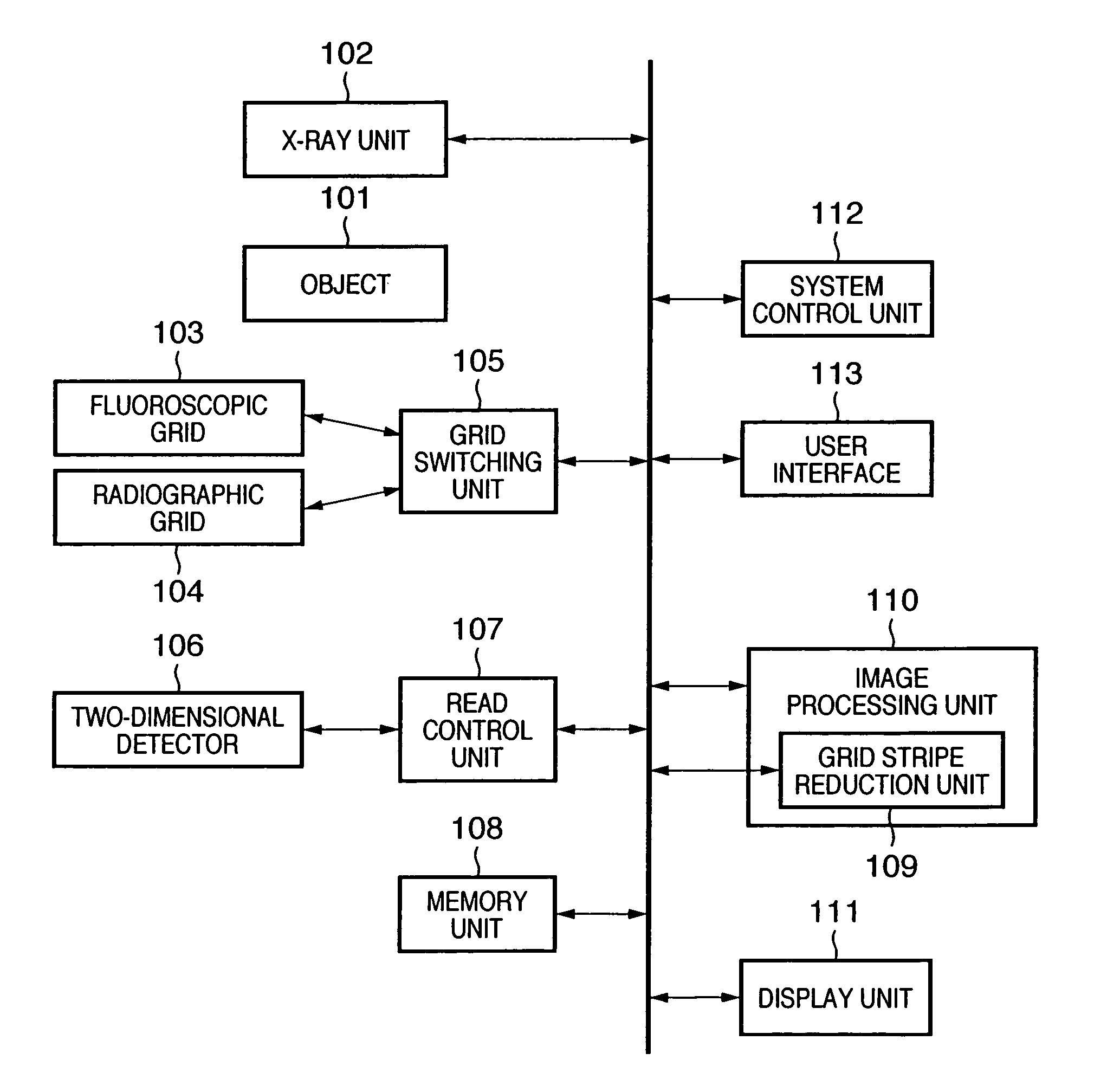
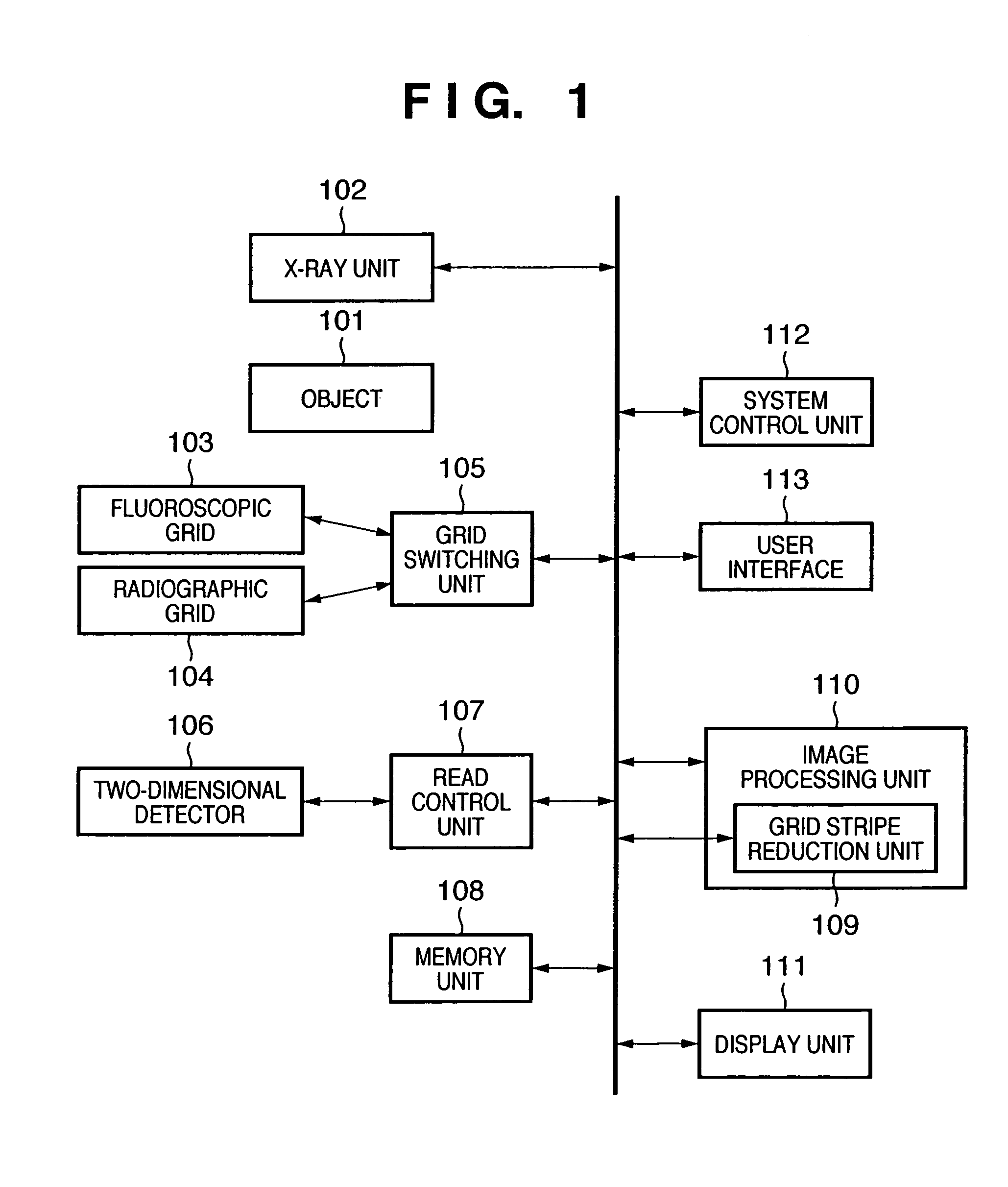
[0028]FIG. 1 is a block diagram showing the arrangement of a radiographic system according to the first embodiment of the present invention. As shown in FIG. 1, the radiographic system according to this embodiment includes an X-ray unit 102 which irradiates an object 101 with radiation (X-rays), a grid switching unit 105 which switches between a fluoroscopic grid 103 and a radiographic grid 104, a two-dimensional detection unit 106 which detects the X-rays through a grid, a read control unit 107 which converts the X-rays detected by the two-dimensional detection unit 106 into an optical image (image), a memory unit 108 which stores the image, an image processing unit 110 having a grid stripe reduction unit 109 which reduces grid stripes on the image by the fluoroscopic grid 103 or radiographic grid 104, a display unit 111 which displays the image, a system con...


PUM


Abstract

This invention provides a radiographic apparatus and method, which can suitably set a grid in radiography or fluoroscopy and execute fluoroscopy or radiography of an object under optimum imaging conditions. The radiographic apparatus includes an X-ray unit (102) which irradiates an object with radiation (X-rays), a two-dimensional detector (106) which detects, through a grid, the radiation which has passed through the object, and a read control unit (107) which acquires an image of the object from the detected X-rays. The apparatus further includes a user interface (113) capable of setting imaging conditions such as an X-ray condition, grid condition, and read condition, a grid switching unit (105) which selects one of a plurality of grids on the basis of the set imaging conditions, and a grid stripe reduction unit (109) which reduces grid stripes generated on the image by the grid.

Description

FIELD OF THE INVENTION[0001]The present invention relates to a radiographic technique for switching a grid between fluoroscopy and radiography.BACKGROUND OF THE INVENTION[0002]Conventionally, a grid moving mechanism for a radiographic / fluoroscopic bed (e.g., patent reference 1: Japanese Patent Laid-Open No. 61-220631), a casetteless fluoroscopic / radiographic apparatus (e.g., patent reference 2: Japanese Patent Laid-Open No. 2-191936), and a fluoroscopic / radiographic apparatus (e.g., patent reference 3: Japanese Patent Laid-Open No. 3-53238) are known as techniques using different grids in fluoroscopy (moving image formation) and radiography (still image formation) in a fluoroscopic / radiographic apparatus.[0003]Patent reference 1 discloses a technique related to a reciprocating grid system, that is, a grid moving mechanism for a fluoroscopic / radiographic bed. This system is characterized by comprising a reciprocal reciprocating mechanism capable of transmitting a reciprocation force ...

Claims


Application Information

Patent Timeline
Patent Type & Authority Patents(United States)
IPC IPC(8): H05G1/58A61B6/00A61B6/06H05G1/64
CPCA61B6/06A61B6/5235A61B6/4291A61B6/5252
Inventor TSUJI, OSAMU
Owner CANON KK
Learn More