
Phase distortion using MOS nonlinear capacitance

a capacitance and phase distortion technology, applied in the field of phase, can solve the problems of limiting the improvement in performance these blocks can provide, reducing the performance of rf amplifiers such as power amplifiers, and rf amplifiers that are typically subject to both phase distortion and amplitude distortion in the rf signal

Active Publication Date: 2006-09-19
MAXIM INTEGRATED PROD INC
View PDF2 Cites 7 Cited by
  • Summary
  • Abstract
  • Description
  • Claims
  • Application Information

AI Technical Summary

Problems solved by technology

RF amplifiers such as power amplifiers are typically subject to both phase distortion and amplitude distortion in the RF signal.
Such distortion is characterized by increasing distortion at increasing instantaneous RF signal magnitudes.
The gain and phase distortion are not independent, which limits the improvement in performance these blocks can provide.
Currently, independent gain distortion circuits are available, but independent RF phase distortion circuits are not.

Method used


Image

  • Phase distortion using MOS nonlinear capacitance
  • Phase distortion using MOS nonlinear capacitance
  • Phase distortion using MOS nonlinear capacitance

Examples


Embodiment Construction

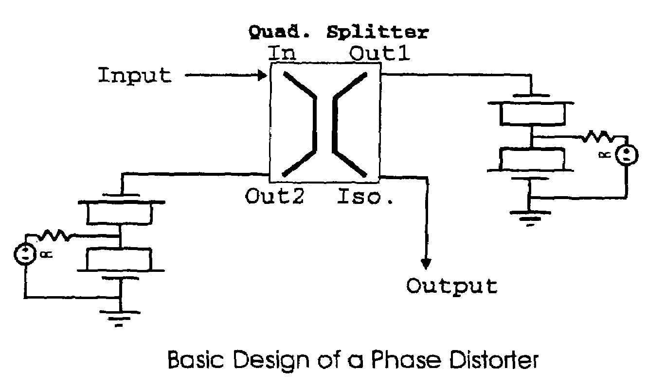
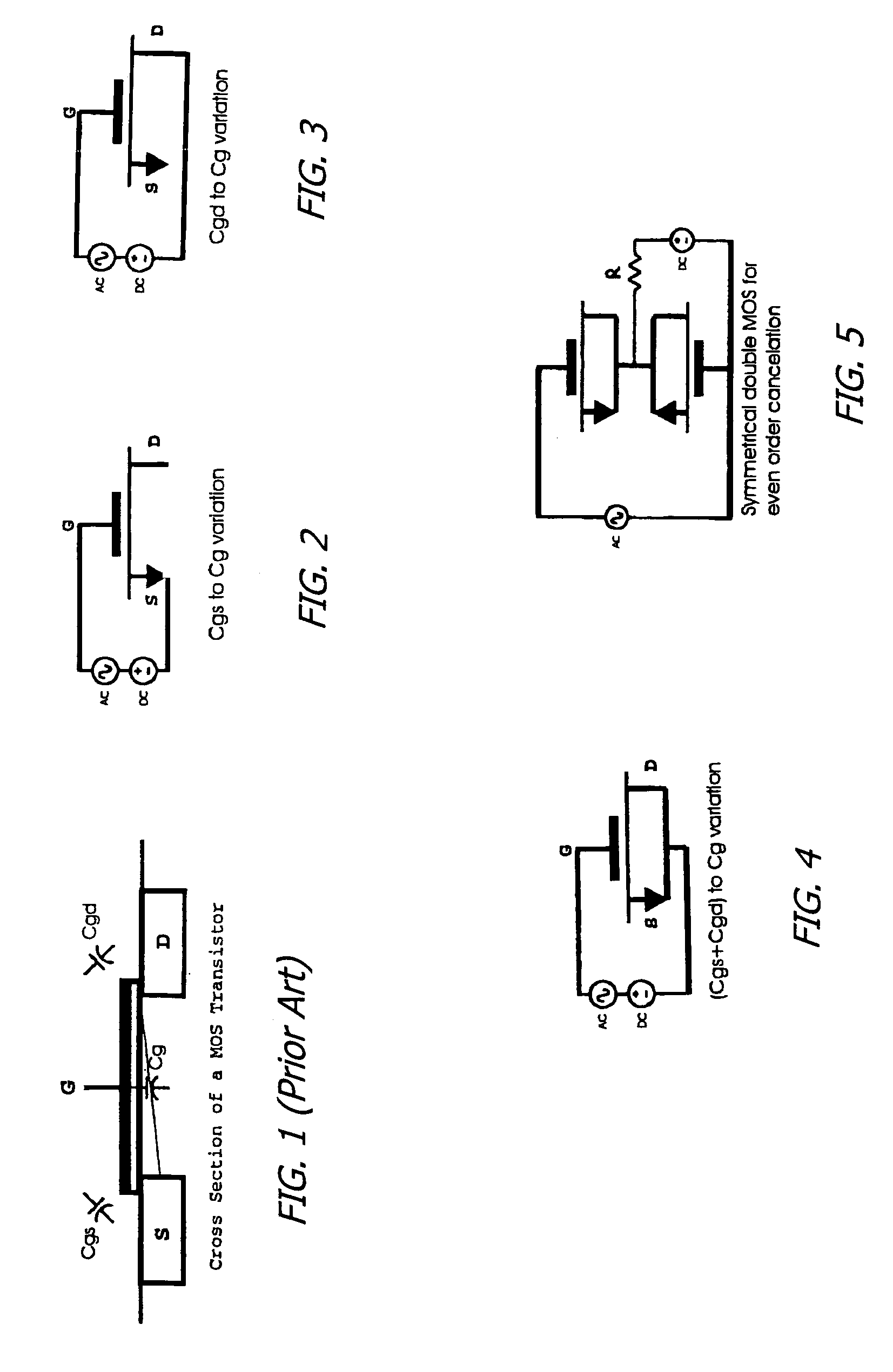
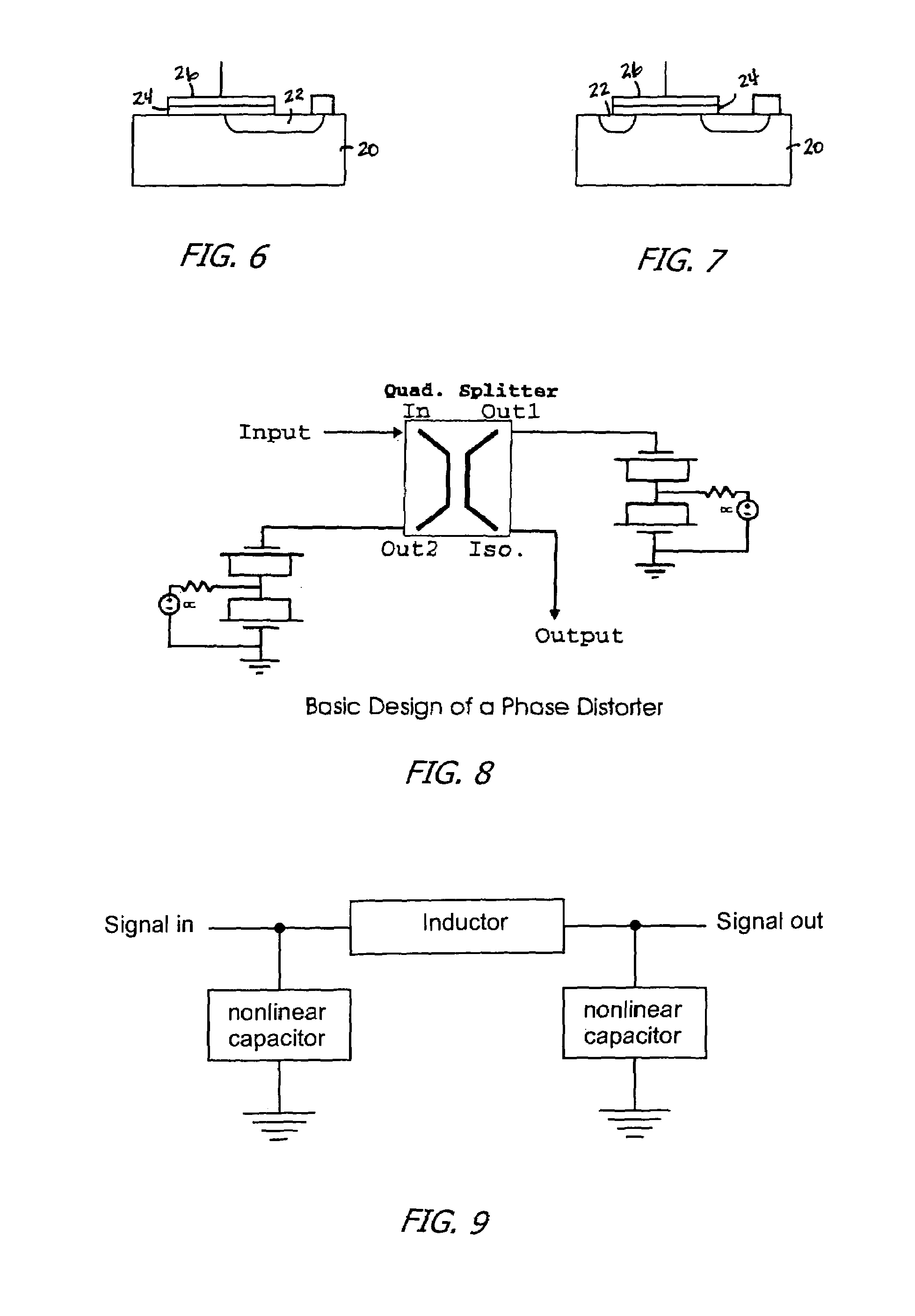
[0017]The present invention comprises phase distorters utilizing MOS type devices to create a nonlinear response to a large input signal. The nonlinear response can be characterized as an impedance that varies as a function of the input power. The MOS device creates an impedance variation that is more reactive than a similar impedance variation created by other devices such as BJT transistors. This more “reactive” variation facilitates the design of phase distorters for use in pre / post-distortion applications. While certain pre / post-distortion circuits that are sensitive to an impedance that varies as a function of the input power are subsequently disclosed herein, it is to be understood that such circuits are exemplary only, and other distortion circuits will be obvious to those skilled in the art.

[0018]The impedance of a MOS transistor varies as a function of the instantaneous input signal voltage. This creates distortion around the applied signal's frequency and facilitates the d...


PUM


Abstract

RF phase distortion circuits and methods for controllably phase distorting an RF signal based on amplitude of the RF signal. An MOS device is provided having a body of a first conductivity type and at least one region of a second conductivity type in the body, with a conductive layer over at least part of the body and the region of the second conductivity type and insulated therefrom. The MOS device may be coupled into a phase distortion circuit individually or in back-to-back pairs and biased to invert the body under the conductive layer for small signal amplitudes and not for large signal amplitudes, or to not invert the body under the conductive layer for small signal amplitudes and to invert the body under the conductive layer for large signal amplitudes. Various embodiments are disclosed.

Description

BACKGROUND OF THE INVENTION[0001]1. Field of the Invention[0002]The present invention relates to the field of amplitude and phase distortion circuits, and more particularly to phase distortion circuits for distorting the instantaneous phase of a signal.[0003]2. Prior Art[0004]RF amplifiers such as power amplifiers are typically subject to both phase distortion and amplitude distortion in the RF signal. Such distortion is characterized by increasing distortion at increasing instantaneous RF signal magnitudes. To reduce this distortion, the RF signal may be subjected to offsetting pre-distortion to try to negate the effects of the distortion. Similar effects can also be obtained by applying an offsetting post-corrective distortion to an already distorted RF signal. Preferably, independent control of phase distortion and amplitude distortion would be provided to simplify the pre-distortion or post-distortion process and improve its effectiveness.[0005]An ideal phase distorter would be ...

Claims


Application Information

Patent Timeline
Patent Type & Authority Patents(United States)
IPC IPC(8): H04B7/165
CPCH03F1/3205H03F1/56H03F1/3276H03F2200/198
Inventor SZCZESZYNSKI, GREGORY KRZYSTOFMOURANT, JEAN-MARC
Owner MAXIM INTEGRATED PROD INC
Learn More