
Device and method for performing information processing using plurality of processors

a technology of information processing and processors, applied in the direction of memory adressing/allocation/relocation, input/output to record carriers, instruments, etc., can solve the problem of lowering the performance of the device as a whole, and achieve the effect of low burden, shared memory and shared memory paths, and low cos

Inactive Publication Date: 2006-09-19
HITACHI LTD
View PDF27 Cites 12 Cited by
  • Summary
  • Abstract
  • Description
  • Claims
  • Application Information

AI Technical Summary

Benefits of technology

[0007]In the conventional technique described above, the exchange of control information between MPs is accomplished via a shared memory, and the MP on the receiving side periodically polls a specified region of the shared memory. This polling of the shared memory places a not inconsiderable burden on the receiving side MP. Furthermore, as the number of MPs increased, frequent repetition of the reading of the shared memory by the plurality of MPs tends to cause a performance bottleneck in the shared memory or a performance bottleneck in the shared memory path; as a result, there is a possibility that the performance of the device as a whole will be lowered.
[0008]Accordingly, it is an object of the present invention to allow the reception of information among processors by a method that places little burden on the receiving side processor.
[0009]Another object of the present invention is to allow the reception of information among processors without lowering the performance of the device as a whole.

Problems solved by technology

Furthermore, as the number of MPs increased, frequent repetition of the reading of the shared memory by the plurality of MPs tends to cause a performance bottleneck in the shared memory or a performance bottleneck in the shared memory path; as a result, there is a possibility that the performance of the device as a whole will be lowered.

Method used


Image

  • Device and method for performing information processing using plurality of processors
  • Device and method for performing information processing using plurality of processors
  • Device and method for performing information processing using plurality of processors

Examples


embodiment 1

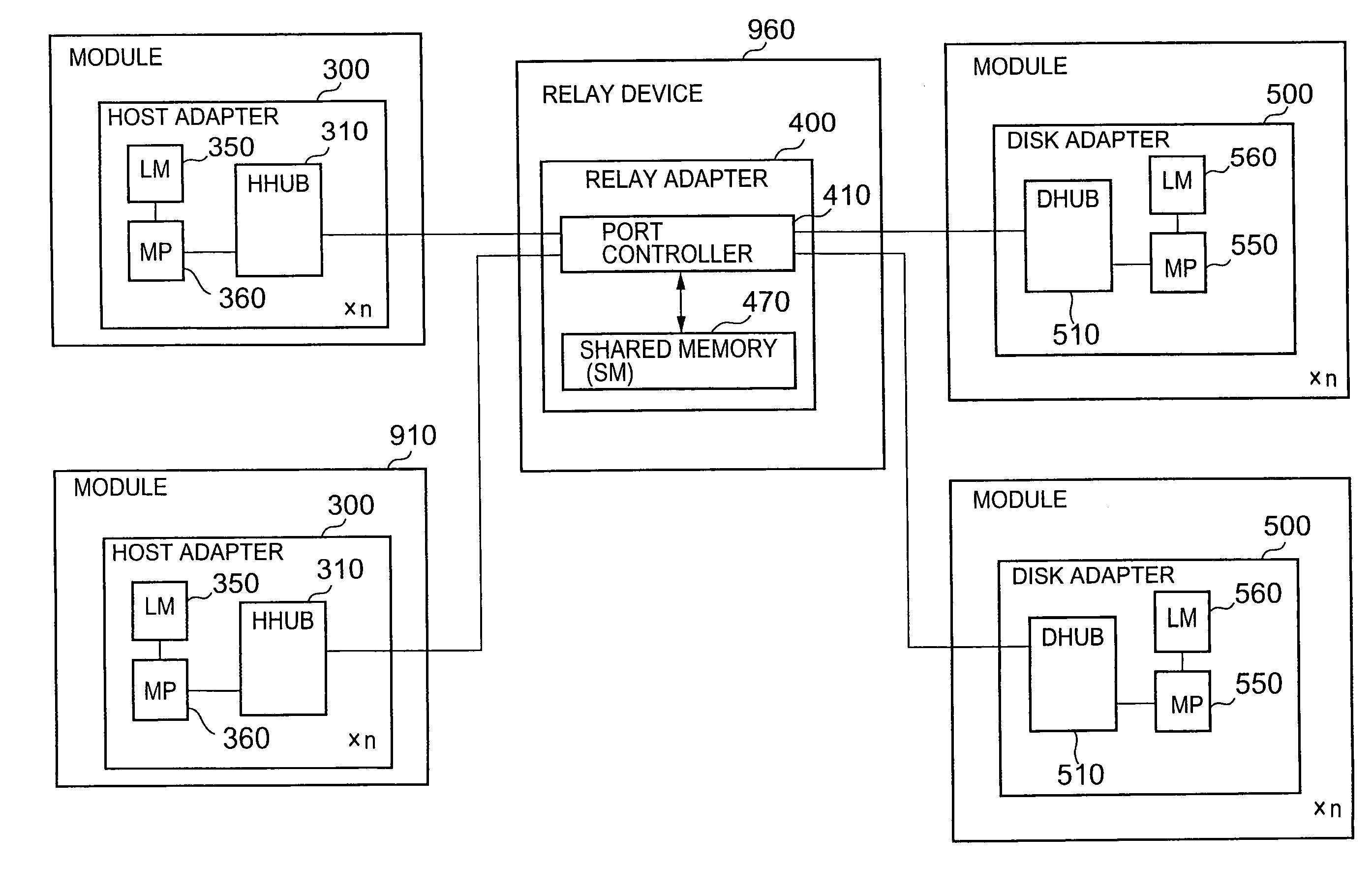
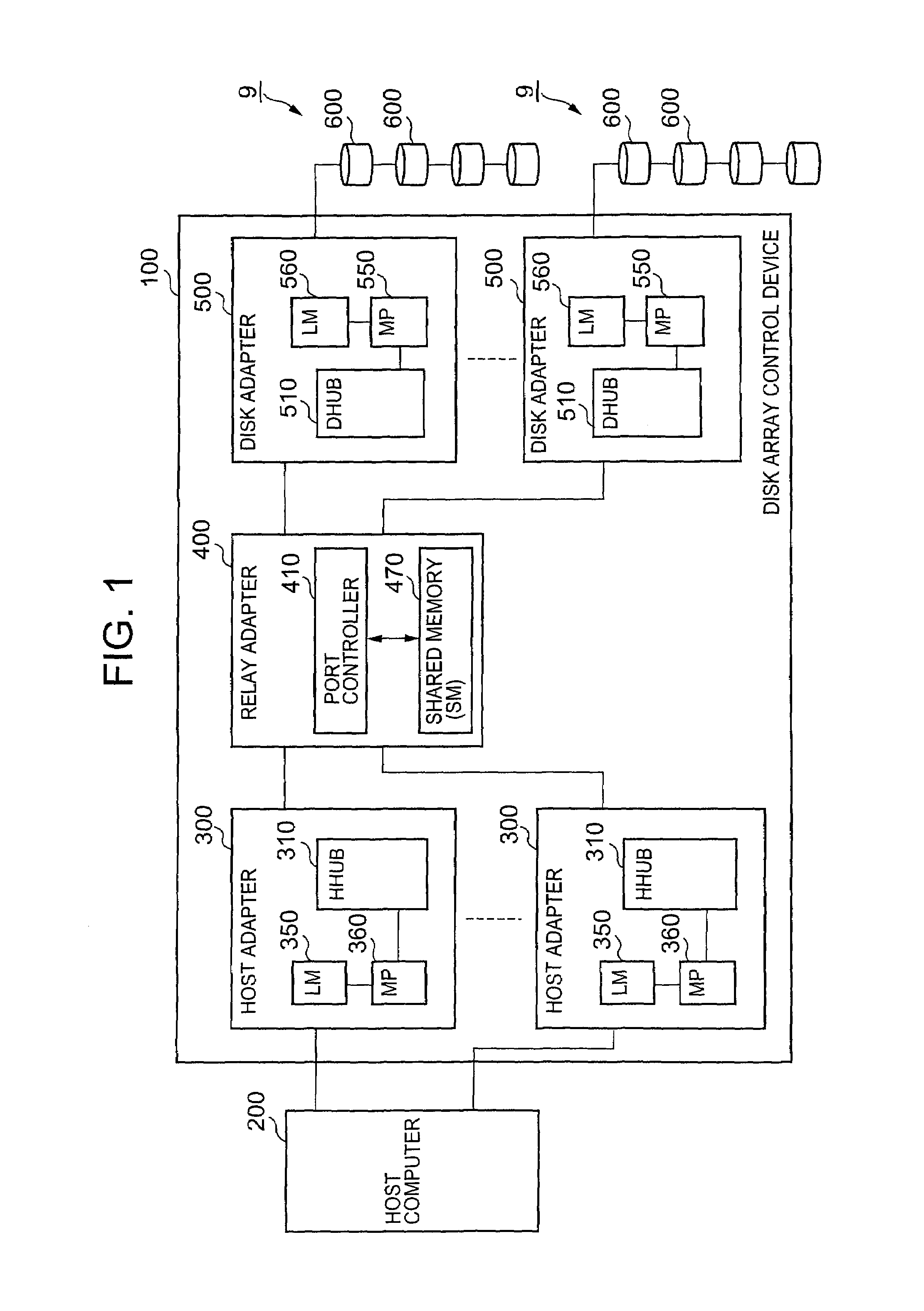
[0070]FIG. 1 shows the construction of a disk array control device constituting the first embodiment of the present invention.

[0071]The disk array control device 100 shown in this figure is (for example) a RAID (redundant array of independent inexpensive disks) device; one or a plurality of host computers 200 and a plurality of physical disk groups 9 are connected to this device 100.

[0072]The host computer (hereafter appropriately abbreviated to “host”) 200 is (for example) a personal computer, work station or the like, and is a computer machine that comprises a CPU (central processing unit), a memory and the like. Various functions are realized by the execution of various types of programs by the CPU of the host 200. For example, the host 200 transmits write commands that write desired data into the physical disk groups 9 (e. g., logical devices or logical recording regions called logical units), and read commands that read desired data from the physical disk groups 9, to the disk ...

embodiment 2

[0197]In the abovementioned first embodiment, command transfer is performed using a relay part master system in which the relay adapter that transfers the commands is the master, and the reception side adapter (e. g., the disk adapter 500) that receives the commands is the slave. However, in the second embodiment that will be described below, command transfer is performed by a reception side master system in which the relay adapter is the slave, and the reception side adapter is the master. This will be described in detail below.

[0198]FIG. 15 shows an example of the construction of the disk adapter in this second embodiment of the present invention. Furthermore, in this figure, parts that have the same function as in the disk adapter 500 shown in FIG. 5 are labeled with the same reference numbers. Furthermore, in the following description, the description of parts that duplicate the first embodiment will be abbreviated or omitted.

[0199]A path interrupt control part 903 which receive...

third embodiment

[0210]Next, a third embodiment of the present invention will be described.

[0211]In this third embodiment, the respective MPs (e. g., the host MP 360A) store read commands sent by the direct LM write system or indirect LM write system in desired storage destination LMs (e. g., the disk side LM 550A), so that messages that are read from these LMs are received.

[0212]This third embodiment is an example of application of the abovementioned first embodiment. Specifically, when the MPs on the command transmission side of the read commands write these read commands into the command reception side LMs of the command reception side MPs by the direct LM write system or indirect LM write system, the command reception side MPs acquire messages destined for the command transmission side MPs from the command reception side LMs in response to these read commands, and store these messages in the command transmission side LMs of the command transmission side MPs by the direct LM write system or indir...


PUM


Abstract

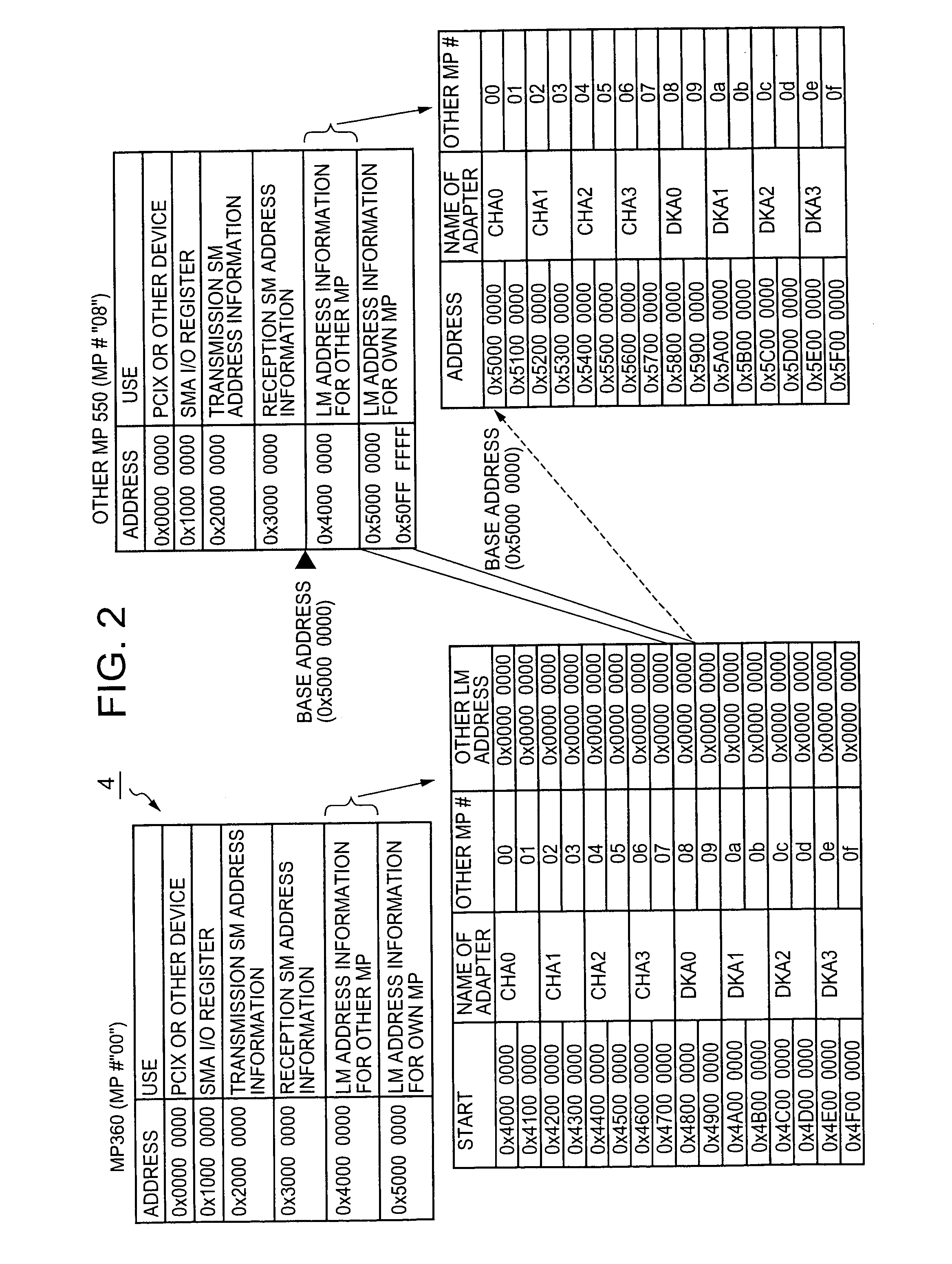
The present invention makes it possible to transfer information between processors by a method that places little burden on the reception side processors. The information processing device is a device that processes information using a plurality of processors, comprising one or more first processors that have one or a plurality of local memories, and one or more second processors that write write information directly into the local memory that the target first processor has. The second processors store address maps in which local memory addresses for the first processors are recorded; these second processors acquire local memory addresses from these address maps, and write write information into the acquired local memory addresses.

Description

CROSS-REFERENCE TO RELATED APPLICATION[0001]This application relates to and claims priority from Japanese Patent Application No. 2003-396786 filed on Nov. 27, 2003, the entire disclosure of which is incorporated herein by reference.BACKGROUND OF THE INVENTION[0002]1. Field of the Invention[0003]The present invention relates to a technique for performing information processing using a plurality of processors, and more concretely relates to (for example) a memory control device that is installed in a RAID (redundant array of independent inexpensive disks) system.[0004]2. Description of the Related Art[0005]One type of device for performing information processing using a plurality of processors is (for example) a memory control device which controls access from a host device to a memory device that has a plurality of physical disks arranged in the form of an array. For example, two or more channel adapters that are used for communications with the host device and two or more disk adapt...

Claims


Application Information

Patent Timeline
Patent Type & Authority Patents(United States)
IPC IPC(8): G06F13/14G06F12/10G06F3/06G06F12/00G06F13/38G06F15/16G06F15/167G06F15/17G06F15/177
CPCG06F15/16G06F13/385
Inventor MINOWA, NOBUYUKI
Owner HITACHI LTD
Learn More