Hot blow forming control method

a control method and hot blow technology, applied in the direction of manufacturing tools, heat treatment equipment, shaping tools, etc., can solve the problems of difficult or impractical management of the actual temperature of the sheet material at the target level

Active Publication Date: 2006-09-26
GM GLOBAL TECH OPERATIONS LLC
View PDF9 Cites 21 Cited by
  • Summary
  • Abstract
  • Description
  • Claims
  • Application Information

AI Technical Summary

Benefits of technology

[0010]Preferably, the sheet metal hot blow forming operation is performed on tooling facilitating control of the temperature of the forming environment. The complementary forming tools are suitably fixed to platens of a press in which the tools are moved from an open position for insertion of a preheated workpiece to a closed position in which edges of the sheet material blank are gripped between the tools. One tool provides the forming surface opposite one side of the sheet and the other tool defines a chamber on the opposite side of the sheet for controlled application of pressurized working gas. It is preferred that the tools be independently internally heated and insulated for better temperature control of the forming operation. The practice of the method of this invention benefits from sensing and use of the operative temperature of the blank being formed to determine the optimal gas pressure for rapid, but defect free shaping of the part.
[0013]This invention is a closed loop control process that changes the applied pressure-time cycle to account for changes in temperature affecting the shape change of the workpiece. A location is identified, for example at the forming tool surface, for temperature monitoring for the purpose of suitably controlling forming pressure for shape change of the workpiece. The goal of the process is to adjust and control working gas pressure to maintain a desired evolution of part shape so that the fastest possible gas pressurization cycle is maintained that does not damage the sheet material.

Problems solved by technology

However, as described above, it is sometimes difficult or impractical to manage the actual sheet material temperature at the target level during hour to hour, day to day forming operations.

Method used


Image

  • Hot blow forming control method
  • Hot blow forming control method
  • Hot blow forming control method

Examples


Embodiment Construction

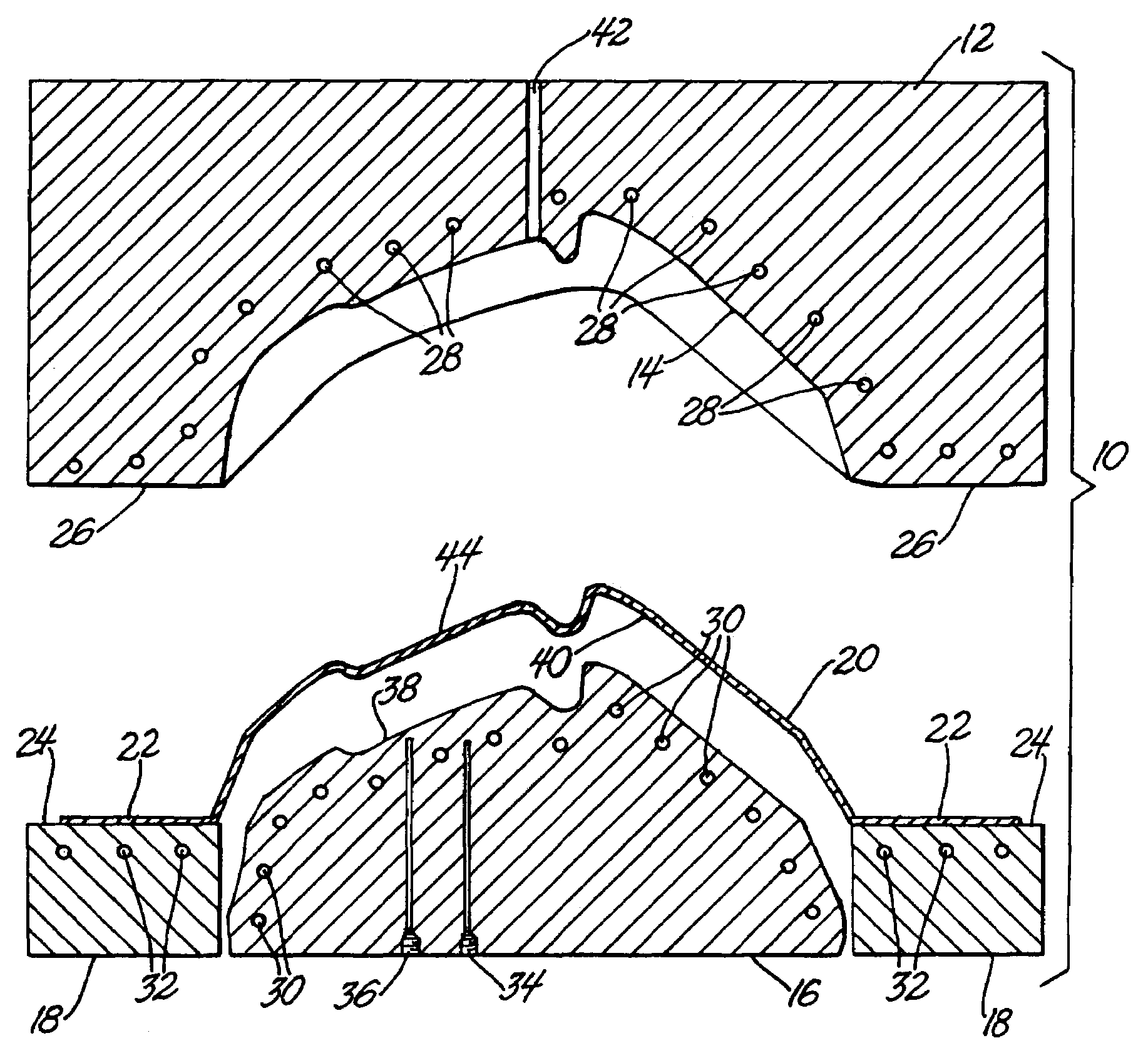
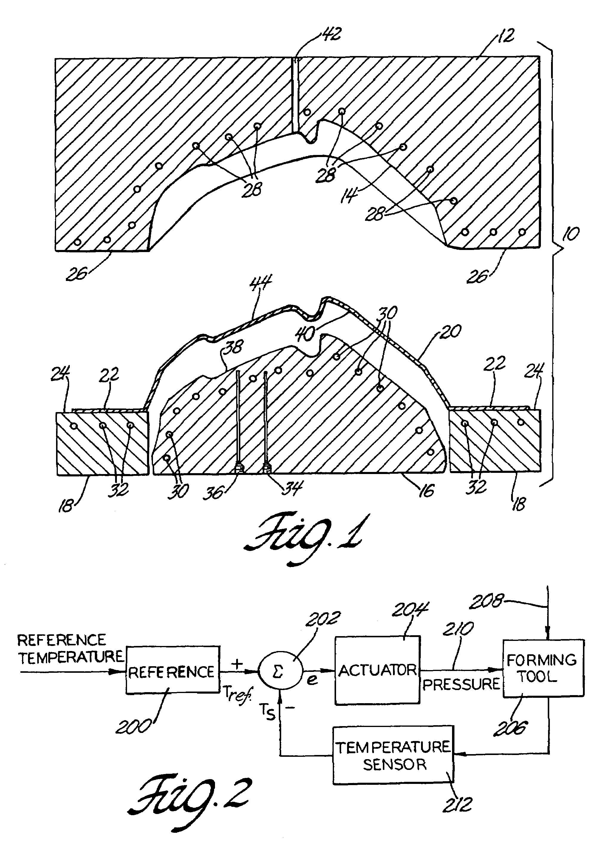
[0020]This invention is applicable to manufacturing operations in which substantially identical blanks of a sheet material are to be formed into like blow formed products, using a pressurized working gas, on a heated forming tool(s) in a suitable press or mold apparatus. FIG. 1 illustrates heated tooling for the two-stage forming of a preheated blank of very ductile aluminum alloy sheet material into a stretch formed panel. An example of the full two-stage forming of an aluminum alloy sheet material into a formed part will be described. The practice of the subject invention will be illustrated as the method is used during the second stage of the forming of the sheet metal part. However, it is to be understood that the method may be used in single stage hot blow forming processes as well as in either or both stages of a two-stage process.

[0021]FIG. 1 is a side elevation view, in cross-section, of tooling 10 for the hot blow forming of an automobile body panel using a sheet blank of A...


PUM

PropertyMeasurementUnit
temperatureaaaaaaaaaa
pressureaaaaaaaaaa

Abstract

A sheet material is gripped at its edges and hot blow formed by a pressurized working gas against a forming tool surface. The flow characteristics of the material are determined at increasing gas pressures over a range of temperature relevant to the forming operation. A predetermined pressure / time schedule is determined at a reference temperature for rapid shape formation of good parts on a continual basis. The process is then controlled as parts are thus formed by measuring the forming temperature of the parts and correcting the pressure time schedule, using the determined flow characteristics, for the actual temperature to achieve the desired shape evolution of the parts.

Description

TECHNICAL FIELD[0001]This invention pertains to hot blow forming of a sheet material against a forming tool surface using a pressurized working gas to stretch the sheet. More specifically, this invention pertains to a method of controlling the pressure of the working gas in response to a measured temperature, such as the temperature of the forming tool surface, that influences the strain rate of material flow.BACKGROUND OF THE INVENTION[0002]In blow forming, a sheet of formable material is heated to a temperature at which it can be stretched by a pressurized working gas against a heated forming surface. The hot sheet material is gripped at its edges adjacent to the mold or die surface and pressurized air, or other suitable working gas, is applied to one side of the sheet to push and stretch the other side into conformance with the forming surface. The sheet is thus permanently deformed and the gas is vented and the formed sheet product removed from the mold or die. The sheet materia...

Claims


Application Information

Patent Timeline
Patent Type & Authority Patents(United States)
IPC IPC(8): C21D11/00C22F1/04B21D26/02
CPCB21D26/021B21D37/16B21D26/055B21D26/031
Inventor SCHROTH, JAMES GREGORYVERBRUGGE, MARK W.BRADLEY, JOHN ROBERT
Owner GM GLOBAL TECH OPERATIONS LLC
Why Eureka
Try Eureka