Method for applying liner to air duct

a technology for air ducts and liner materials, applied in the direction of liquid/solution decomposition chemical coating, lighting and heating apparatus, heating types, etc., can solve the problems of high cost, difficult installation of new duct systems, time-consuming, etc., and achieve the effect of facilitating good adhesion of liner materials

Active Publication Date: 2006-09-26
DUCT SEAL TECH
View PDF11 Cites 30 Cited by
  • Summary
  • Abstract
  • Description
  • Claims
  • Application Information

AI Technical Summary

Benefits of technology

[0011]The spray device is provided with at least two sets of spring loaded wheels in order to support and maintain the spray head in the center of the duct as the spray device is pulled through the duct by the supply hose. Each set of wheels consists of either three or four wheels that are supported on retractable wheel arms so that the wheels are outwardly biased to force them into rolling contact with the interior surface of the duct. The retractable wheel arms allow the spray device to expand and contract in diameter in response the variation in sizes of duct found within a duct system and thereby allowing the spray device can accommodate a wide range of ducts sizes and shapes and also allowing it to negotiate corners and turns within the duct system as the spray device is pulled through the duct system.
[0014]Optionally, a commercially available electrostatic unit may be employed with the spray head to further facilitate good adherence of the liner material to the interior surface of the duct. The electrostatic unit is optionally provided on the contractor's service vehicle. A first lead of the unit attaches to the duct and provides the duct with an electrical charge. A second lead of the unit attaches to the supply hose and via the supply hose to the spray head, thereby providing the spray on liner material is an opposite electrical charge than that provided by the first lead to the duct. When the electrostatic unit is employed, the liner material is provided with an electrical charge that is opposite to the charge provided on the duct, thus causing the liner material to be drawn to the duct as the liner material is sprayed out of the spray head. Use of the electrostatic unit helps to insure that the liner material is applied to the interior of the duct system in a consistent thickness.

Problems solved by technology

The problems associated with this solution are that installation of a new duct system is time consuming, expensive, and can be extremely difficult, particularly if the building is more than one story high.

Method used


Image

  • Method for applying liner to air duct
  • Method for applying liner to air duct
  • Method for applying liner to air duct

Examples


Embodiment Construction

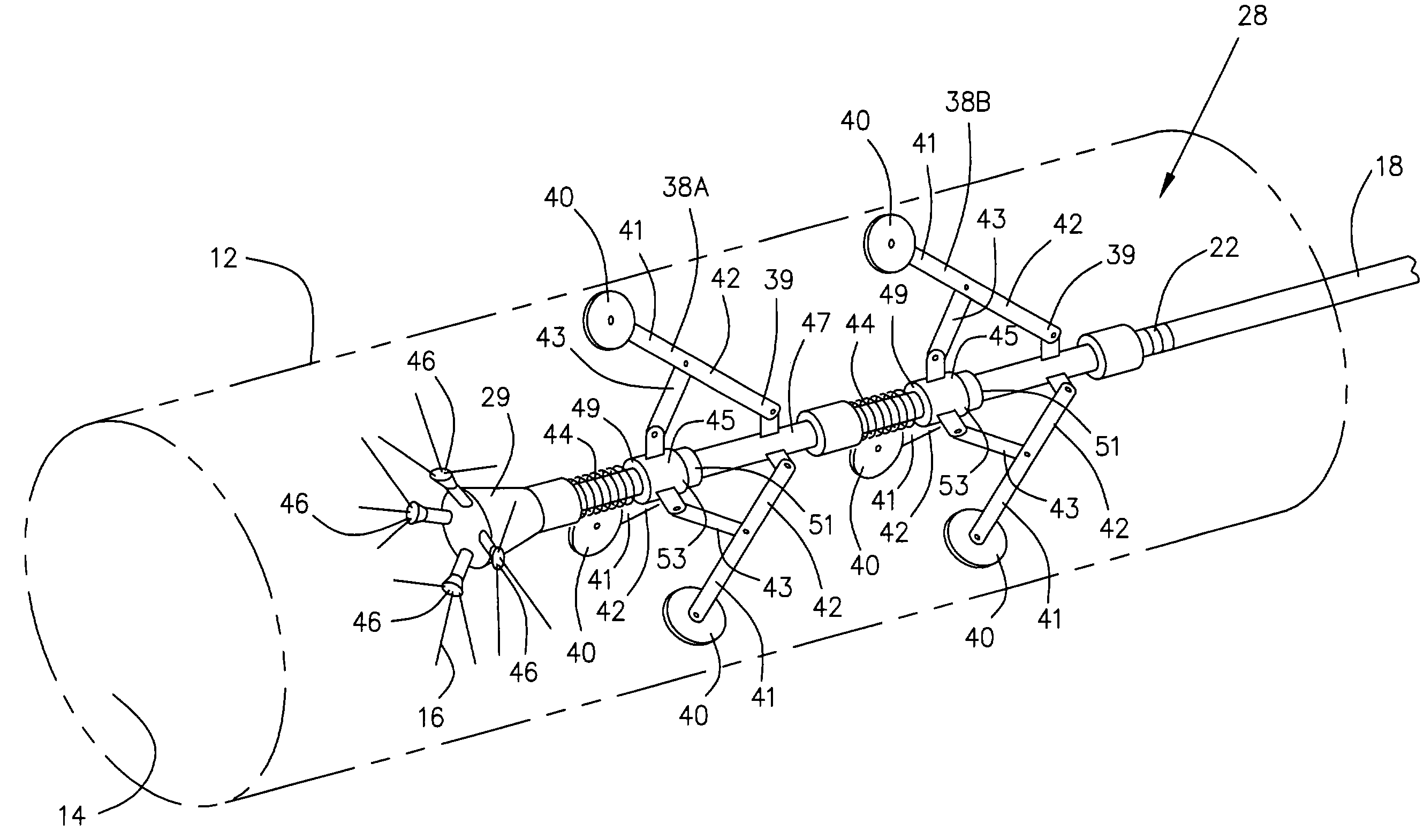
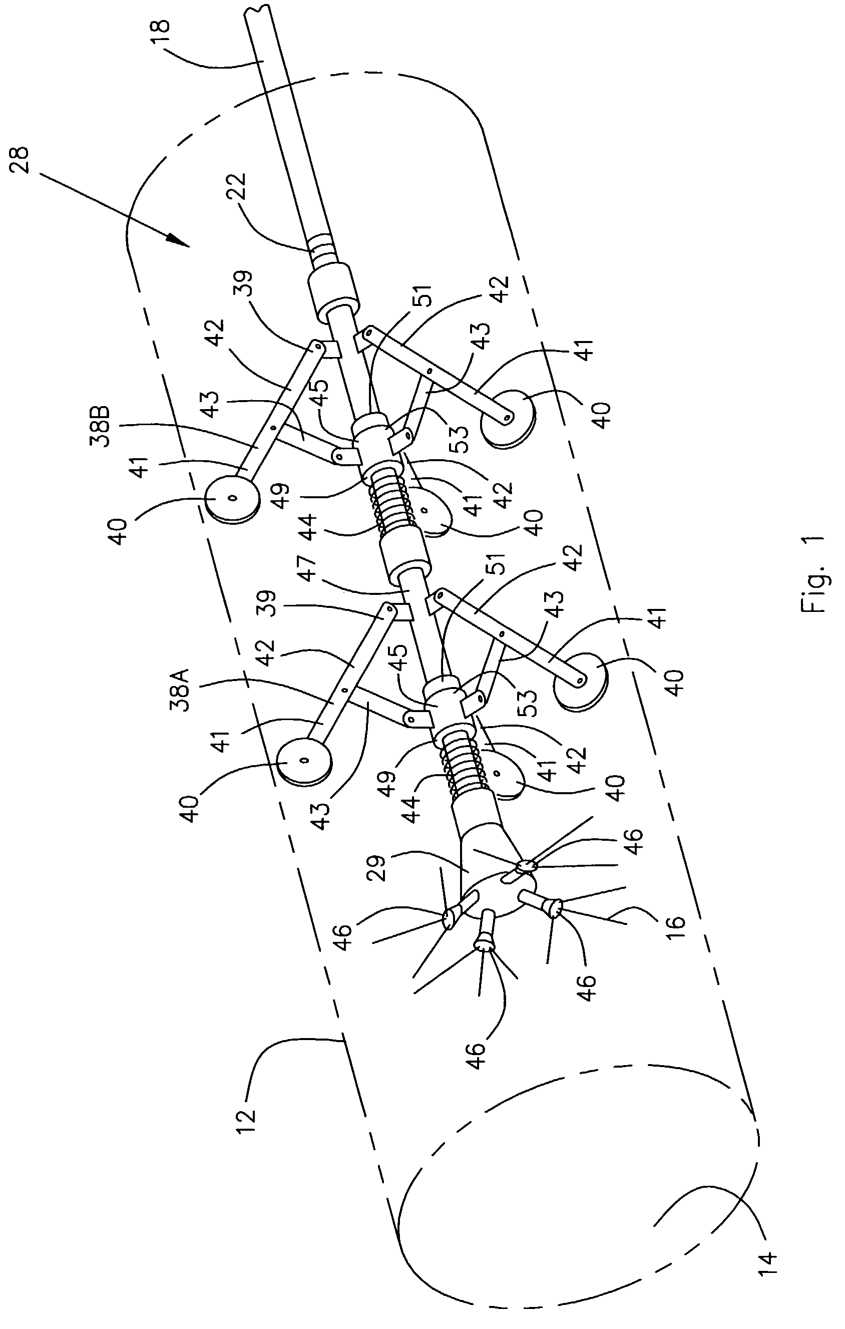
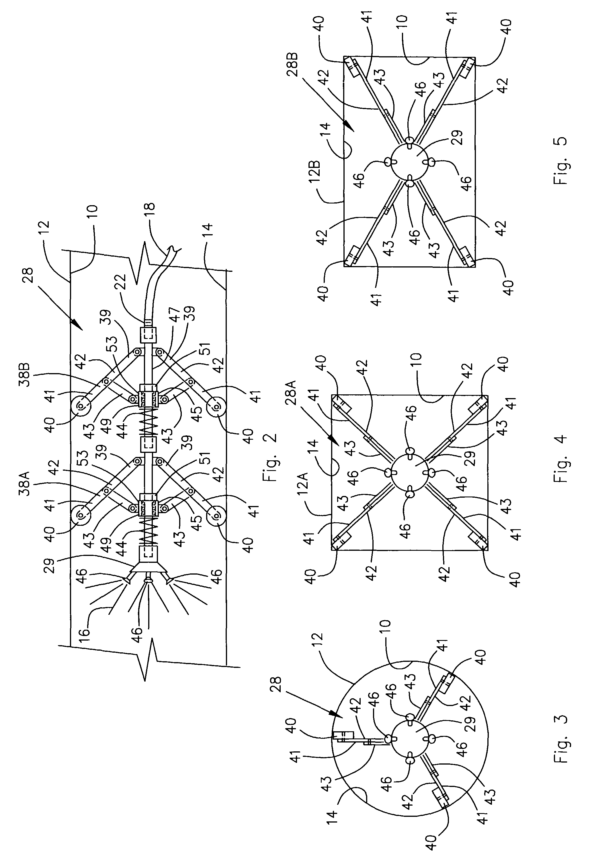
[0021]Referring now to the drawings, and initially to FIG. 6, there is illustrated a system 10 for sealing air ducts 12 of a heating and air conditioning system as a way of remediating the air ducts 12 after the ducts 12 have been damaged due to moisture in the ducts 12 or due to movement in the cement foundation in which the air ducts 12 are located. Specifically, the system 10 is employed to coat the interior surfaces 14 of the ducts 12 of a heating and air conditioning system with a liner material 16 that is similar to the type of coating used for spray-on truck bed liners for vehicles. The preferred liner material is polyurethane that is available from Speedliner, L.L.C. in Tulsa, Okla.

[0022]To install the liner material 16 according to the present method, first a supply hose 18 is fed through a floor duct opening 20 provided at one end 21 of the duct 12 that is to be lined. The supply hose 18 is fed through the duct 12 until a threaded end 22 of the supply hose 18 exists the du...


PUM

PropertyMeasurementUnit
pulling forceaaaaaaaaaa
electrical chargeaaaaaaaaaa
temperaturesaaaaaaaaaa

Abstract

A system for sealing an air duct by coating the interior of the duct with a material similar to the coating used for spray-on truck bed liners. A spray device applies the liner material to the interior surface of the ducts and the spray device is held in the center of the duct by retractable sets of wheels. The spray device is removably attached to a supply hose that provides liner material to the spray device from a storage tank via a supply pump. The supply hose is first fed through the duct, the spray head is attached to the supply hose and the liner material is sprayed onto the duct as the spray head is retracted through the duct. The system can be either computer or manually controlled and can optionally employ an electrostatic unit to put opposite electrical charges on the duct and the liner material.

Description

BACKGROUND OF THE INVENTION[0001]1. Field of the Invention[0002]The present invention relates to a system for sealing air handling ducts, particularly those air ducts that are located in a cement slab floor or under a slab floor.[0003]2. Description of the Related Art[0004]Slab floor buildings normally have the heating and air conditioning air ducts located in the cement slab floor of the building. If the building experiences structural problems, such as a cracked foundation, or has moisture and rust in the ducts, the most common remedy for these problems is to abandon the existing duct system and install a new duct system and new equipment in the ceiling of the building. Then the old abandoned duct system is normally closed off by pouring cement into the duct openings.[0005]The problems associated with this solution are that installation of a new duct system is time consuming, expensive, and can be extremely difficult, particularly if the building is more than one story high.[0006]...

Claims


Application Information

Patent Timeline
Patent Type & Authority Patents(United States)
IPC IPC(8): B05D1/02B05D7/22
CPCB05B13/06F24F13/0245B05D7/222F16L55/1645B05B5/025B05D1/02
Inventor ROBERTS, GREGORY W.
Owner DUCT SEAL TECH
Why Eureka
Try Eureka