Control circuit with tracking turn on/off delay for a single-ended forward converter with synchronous rectification

a control circuit and forward converter technology, applied in the direction of electric variable regulation, process and machine control, instruments, etc., can solve the problems of reducing the reducing the overall efficiency of the converter, and high dissipative losses

Active Publication Date: 2006-09-26
SEMICON COMPONENTS IND LLC
View PDF6 Cites 17 Cited by
  • Summary
  • Abstract
  • Description
  • Claims
  • Application Information

AI Technical Summary

Benefits of technology

[0036]In embodiments the controller includes a first secondary power device, coupled to a first terminal of the secondary coil and having a first voltage with a rising threshold-point and a falling threshold-point, and a second secondary power device, coupled to a second terminal of the secondary coil and having a second voltage with a rising threshold-point and a falling threshold-point. The first and second secondary power devices are coupled to the control logic. The control logic is operable to synchronize one of the rising threshold-point of the first voltage with the falling threshold-point of the second voltage and the falling threshold-point of the first voltage with the rising threshold-point of the second voltage.
[0037]In embodiments the first terminal of the secondary coil has a terminal voltage, which has a terminal rising and a terminal falling edge. In these embodiments the control logic is capable of synchronizing one of the terminal rising edge with the falling threshold-point of the first secondary power device, and the terminal falling edge with the rising threshold-point of the first secondary power device.

Problems solved by technology

Losses, which occur during the Dwell Time tDT, decrease the efficiency of the converter.
Losses during the Dwell Time are often so large that they significantly reduce the overall efficiency of the converter.
During the intermediate time interval D the current is forced to flow through the parasitic diode of the MOSFET, leading to high dissipative losses.

Method used


Image

  • Control circuit with tracking turn on/off delay for a single-ended forward converter with synchronous rectification
  • Control circuit with tracking turn on/off delay for a single-ended forward converter with synchronous rectification
  • Control circuit with tracking turn on/off delay for a single-ended forward converter with synchronous rectification

Examples


Embodiment Construction

[0053]Embodiments of the present invention and their advantages are best understood by referring to FIGS. 6–14 of the drawings. Like numerals are used for like and corresponding parts of the various drawings.

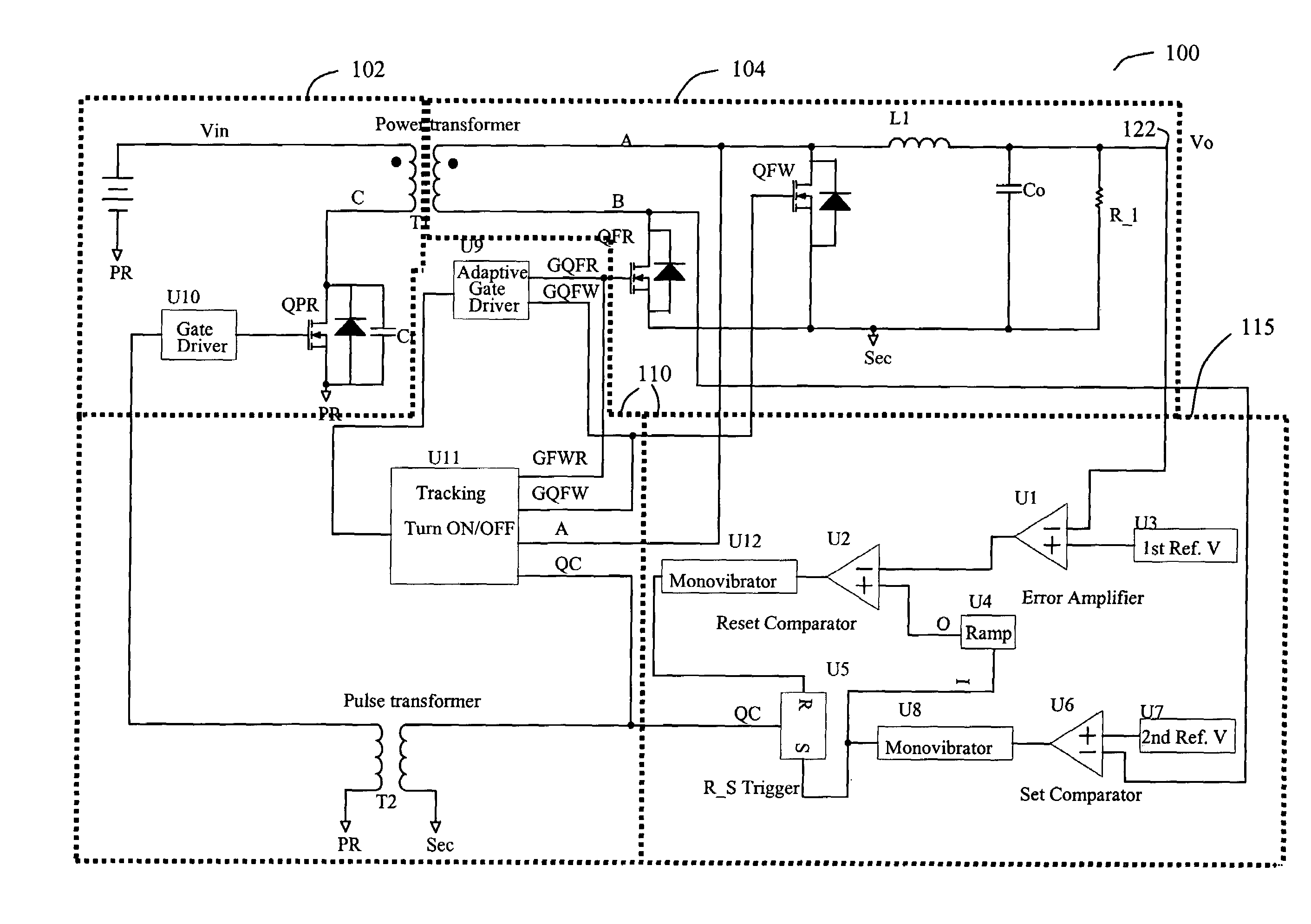
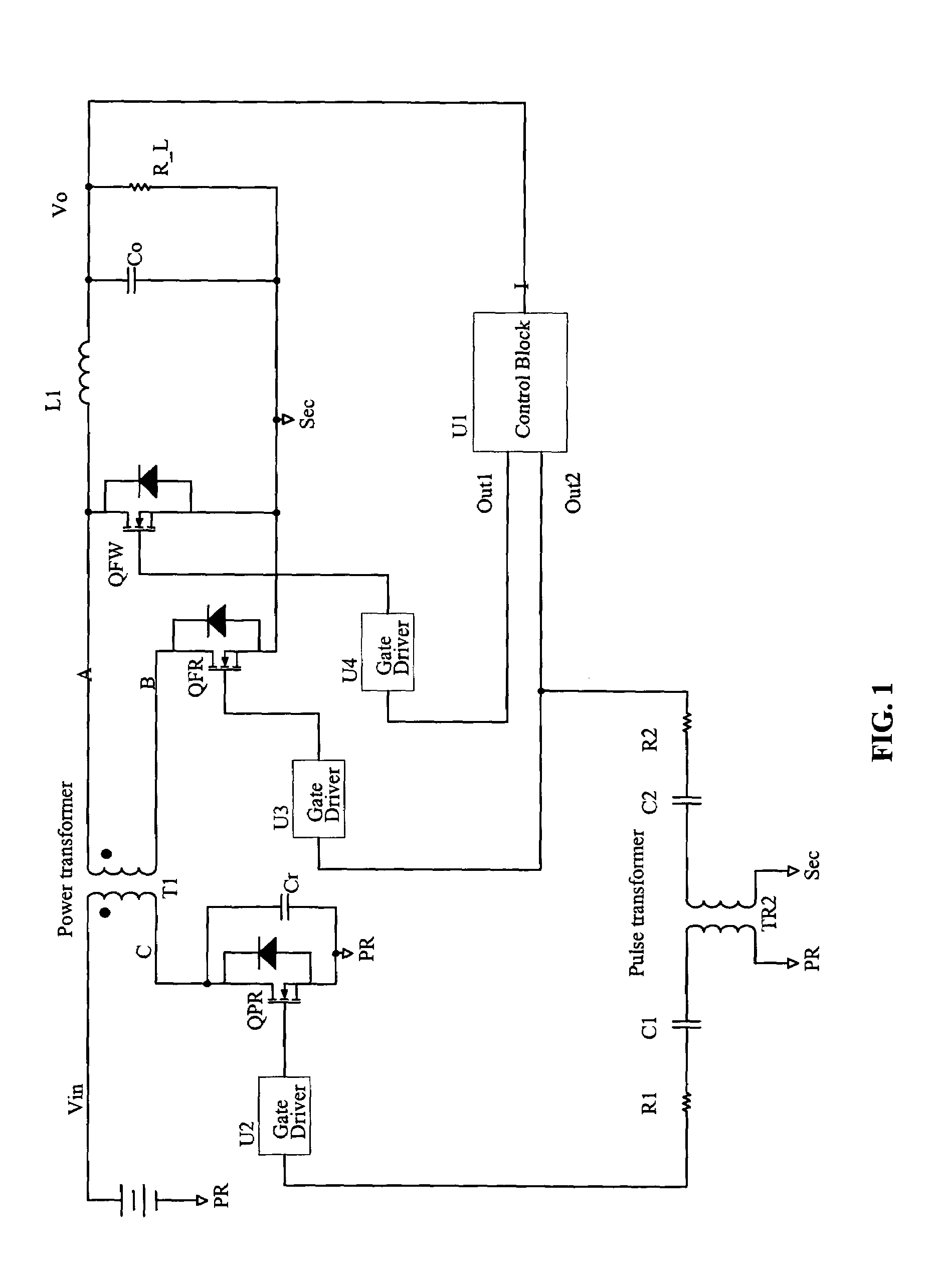
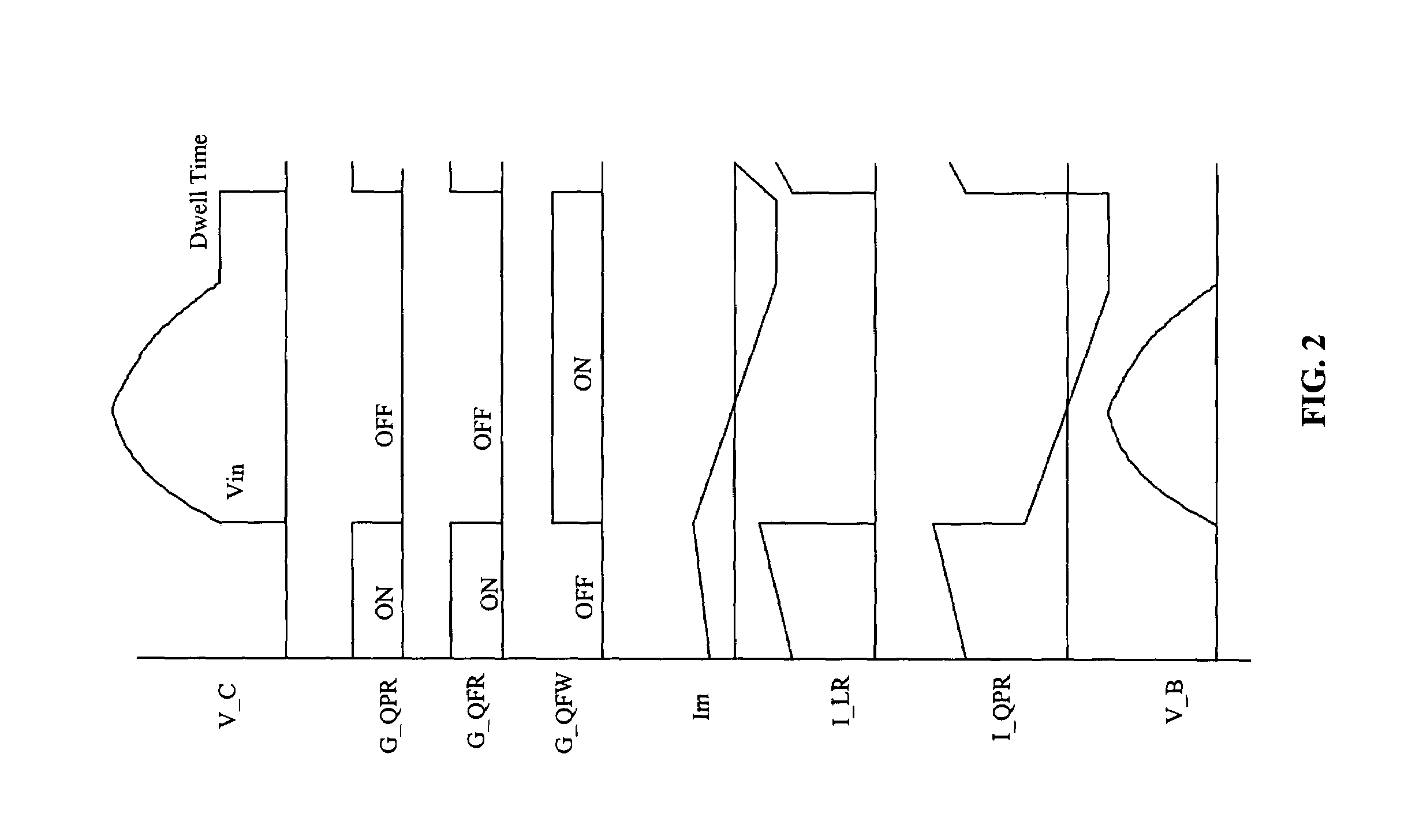
[0054]FIG. 6 illustrates a block diagram of a forward converter 100 with a controller 110 according to embodiments of the invention. The topology of converter 100 includes a primary circuit 102 and a secondary circuit 104. In primary circuit 102 a primary power device QPR controls the flow of current and through that the energy transfer from the input of primary circuit 102 to the output of secondary circuit 104. Primary power device QPR in the illustrated converter is a MOSFET. In other embodiments primary power device QPR can be a bipolar junction transistor or other equivalents. The MOSFETs or transistors can be n-based or p-based semiconductor structures. MOSFET QPR is coupled in parallel to resonant reset capacitor Cr. In some embodiments resonant reset capacitor is an expl...


PUM


Abstract

In a converter-controller the controller includes a primary power device coupled to a primary coil and a resonant reset capacitor in parallel with the primary power device. The controller can switch the primary power device with a variable frequency. The resonant capacitor and the primary coil have a primary resonant cycle. The controller can turn on/off the primary power device for half of the primary resonant cycle. The controller includes a first secondary power device, having a first voltage and a second secondary power device, having a second voltage, each voltages having a rising threshold-point and a falling threshold-point. The first and second secondary power devices are coupled to the control logic and to corresponding terminals of the secondary coil. The controller can synchronize the rising threshold-point of the first voltage with the falling threshold-point of the second voltage or vice versa.

Description

BACKGROUND[0001]1. Field of Invention[0002]The present invention relates to forward converters and more particularly to forward DC / DC converters with adjustable resets.[0003]2. Description of Related Art[0004]FIG. 1 illustrates an existing forward converter design with resonant reset. Converters typically have a primary and a secondary circuit. The primary circuit includes a MOSFET QPR, having a resonant reset capacitor Cr, where MOSFET QPR is coupled to a terminal of the primary coil of Power Transformer T1. The other terminal of the primary coil is driven by a DC voltage source Vin. The secondary circuit includes MOSFETs QFR and QFW, and inductor L1.[0005]A function of MOSFET QPR is to control the energy transfer from DC source Vin to load R_L. In the secondary circuit MOSFETs QFR and QFW constitute a control driven synchronous rectification stage. Here the term “control driven” indicates a forced commutation of MOSFETs QFR and QFW, based on the signals generated by the control ci...

Claims


Application Information

Patent Timeline
Patent Type & Authority Patents(United States)
IPC IPC(8): H02M3/335
CPCH02M3/335Y02B70/1433Y02B70/10
Inventor KHASIEV, VICTOR
Owner SEMICON COMPONENTS IND LLC
Why Eureka
Try Eureka