Implant forming method

a three-dimensional, implant technology, applied in the direction of additive manufacturing process, total factory control, programme control, etc., can solve the problems of insufficient reproductivity, difficult to achieve high reproductivity, and difficult to accurately form the bone body with the deficient portion, etc., to achieve excellent reproductivity of the missing portion of the bon

Inactive Publication Date: 2006-09-26
ASAHI KOGAKU KOGYO KK
View PDF31 Cites 32 Cited by
  • Summary
  • Abstract
  • Description
  • Claims
  • Application Information

AI Technical Summary

Benefits of technology

[0017]The present invention is advantageous in that it provides an improved method for forming an implant having an excellent reproductivity of a missing portion of a bone.
[0018]The present invention is also advantageous in that, it provides a method for forming an implant which has an excellent shape suitability to a body of bone having a deficient portion.
[0020]Since the missing portion to fit the deficient portion is estimated based on the symmetrical part, an implant having excellent shape suitability can be obtained.
[0028]Optionally, the estimating includes designing a shape of the implant that matches the shape of the outline of the bone cutting surface on the outer surface of the bone body, the implant having a substantially fixed shape in a direction of thickness thereof, and the modifying includes overlapping the data representing at least the bone cutting surface of the bone body and the data of the implant, and eliminating data of the implant corresponding to a portion overlapping the bone body.

Problems solved by technology

When the shape of the implant is determined in such a manner, however, sufficient reproductivity cannot be obtained.
Regarding the cheek bone or jaw bone, it is more difficult to achieve the high reproductivity.
Since each plate member is relatively thick, it is difficult to form the model of the body of bone having the deficient portion accurately.
However, the actual shape of the body of bone at a surface where the bone is cut is not taken into consideration.
However, there is a limitation in reducing the thickness of each plate member, and it would be difficult to obtain sufficient shape compatibility.
Further, if the thinner plate members are used to form the model, it will take a relatively long time for forming a model.
Therefore, such a method cannot apply to a condition where the deficient condition cannot remain for a considerable period.

Method used


Image

  • Implant forming method
  • Implant forming method
  • Implant forming method

Examples


Embodiment Construction

[0049]Hereinafter, a method of forming a three-dimensional implant according to an embodiment will be described with reference to the accompanying drawings.

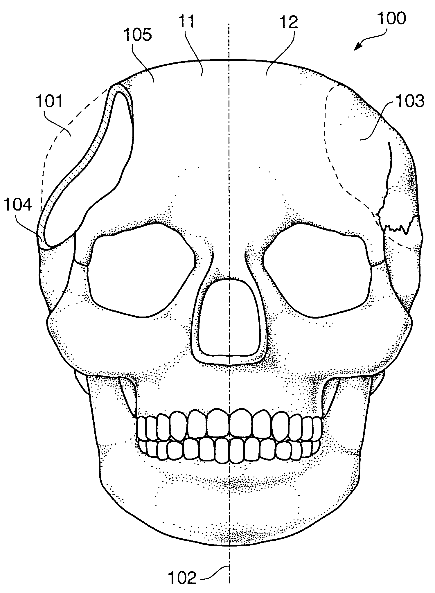
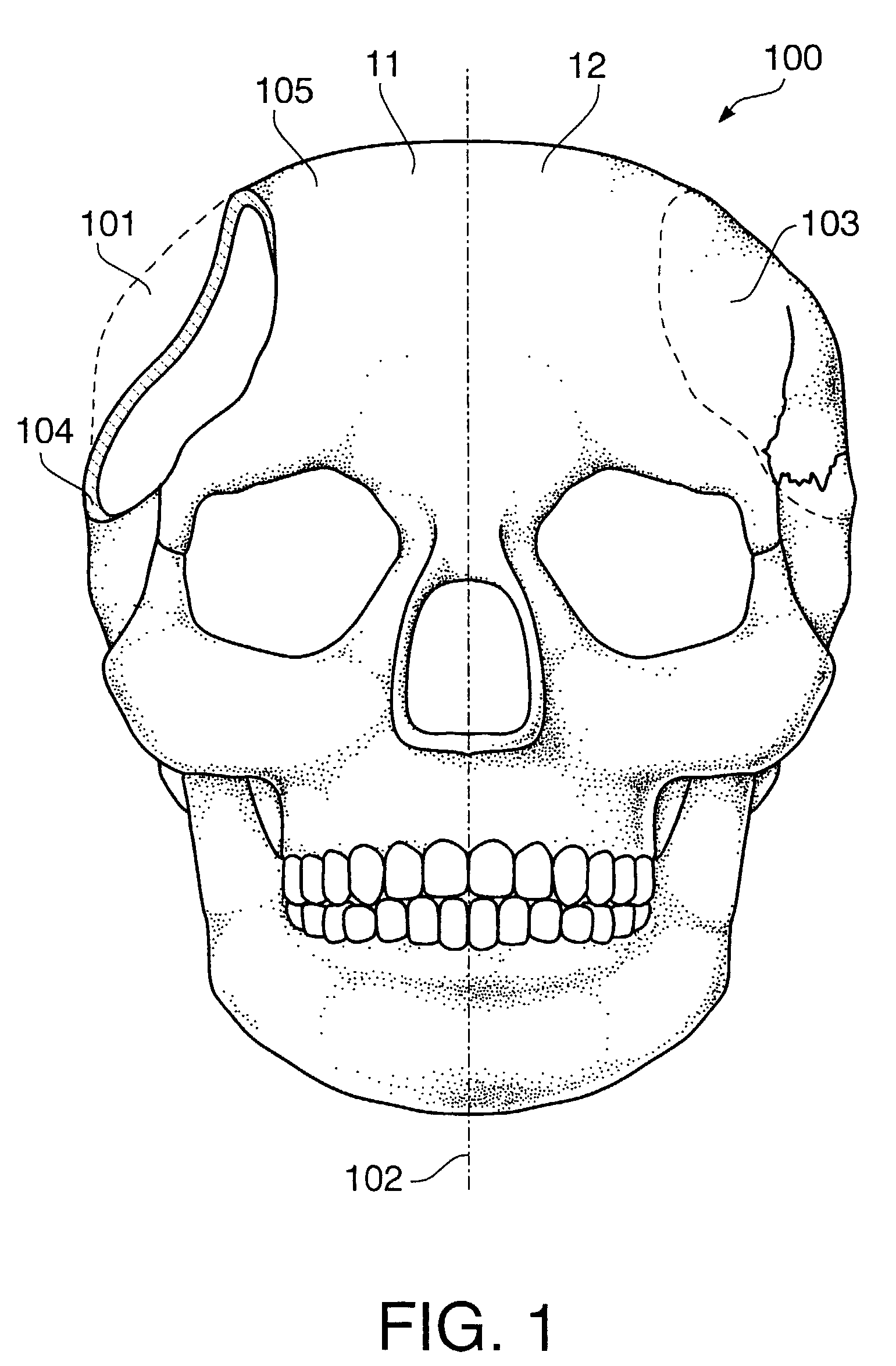
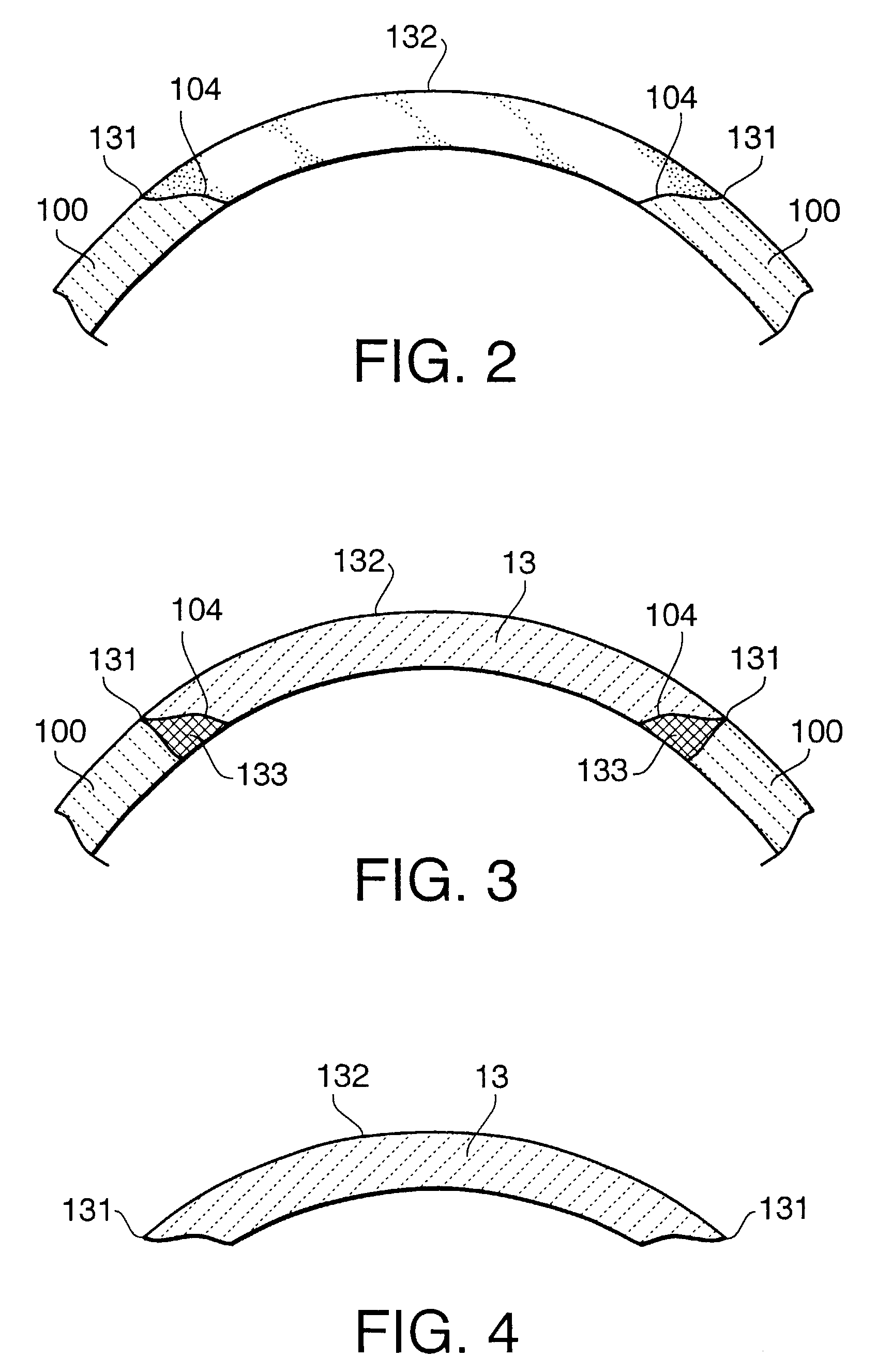
[0050]FIG. 1 shows an image of body of bone (i.e., skull) generated in accordance with three-dimensional data, which is generated based on a plurality of pieces of tomography data. FIG. 2 is a drawing showing a condition where outer surface shape data of a bone that should exist at a bone deficient portion is overlapped with the bone deficient portion, FIG. 3 is a drawing showing a condition where bone deficient portion data with a predetermined thickness is overlapped with the bone deficient portion, and FIG. 4 is a drawing showing bone deficient portion data that has been processed so as to match with the bone cutting surface throughout the entirety in the direction of thickness of the bone. In FIG. 2 through FIG. 4, the upper side shows the outer surface side of the bone three-dimensional data, and the lower side shows the inn...


PUM

PropertyMeasurementUnit
distanceaaaaaaaaaa
distanceaaaaaaaaaa
distanceaaaaaaaaaa

Abstract

An implant designing method to be applied to a body of bone which has a bone deficient portion, wherein the bone being substantially symmetric with respect to a plane of symmetry, includes generating three-dimensional data of the bone based on a plurality of pieces of tomographic data of the bone, and estimating a shape of a bone that is to exist at the bone deficient portion using part of the three-dimensional data corresponding to a symmetrical part of the bone deficient portion.

Description

BACKGROUND OF THE INVENTION[0001]The present invention relates to a method for forming a three-dimensional implant.[0002]Conventionally, when a body of bone, for example bones of skull, cheek bone, jaw bone or the like is partially lost, implants made of artificial material are implanted in the deficient part, and fixed thereat (reconstruction of deficient portion of bone).[0003]In the conventional art of reconstruction of the deficient bone, material and shape of the implant is very important.[0004]Regarding the material, ceramics which have excellent biocompatibility are widely used.[0005]Regarding the shape, the implant is conventionally formed as follows.[0006]Firstly, based on CT (Computed Tomography) data of a body of bone having a deficient portion, a model corresponding to the body of bone is formed using wood or the like. Then, in a deficient portion of the model, paper-mache pulp or the like is filled to obtain a shape of an implant (i.e., the shape of body of bone to be l...

Claims


Application Information

Patent Timeline
Patent Type & Authority Patents(United States)
IPC IPC(8): A61F2/02G06F19/00A61B19/00A61B17/56A61F2/00A61F2/28A61F2/30B29C67/00G05B19/4097
CPCA61F2/2875A61F2/30942B29C67/0081G05B19/4097A61F2002/2817A61F2002/30948A61F2002/30968A61F2002/30971Y10S623/901B29L2031/7532G05B2219/35062G05B2219/35069G05B2219/45168A61F2310/00293B29C64/165B33Y80/00Y02P90/02
Inventor ABE, KEITASHIOTANI, SHINGOKATO, MOTOMASAYOSHIDA, TAKAMITSU
Owner ASAHI KOGAKU KOGYO KK
Why Eureka
Try Eureka