Circuit and method for the input of a start signal for a controller

a start signal and controller technology, applied in the direction of generating/distributing signals, pulse techniques, instruments, etc., can solve the problems of high current consumption of the control unit, inability to yield optimal related art, and emission of a start signal as a wake-up signal to the microcontroller, so as to achieve the effect of simple possibility of detecting the signal state and better processing and comparison

Inactive Publication Date: 2006-09-26
ROBERT BOSCH GMBH
View PDF6 Cites 56 Cited by
  • Summary
  • Abstract
  • Description
  • Claims
  • Application Information

AI Technical Summary

Benefits of technology

[0008]By doing this, in an advantageous manner, a reduction in the no-signal current consumption of the control unit may be achieved in connection with the example circuit according to the present invention, while at the same time the real-time capability with respect to recording the signals during the first energy-poor state, i.e., the sleep mode or standby mode is maintained, to a great extent.
[0010]This also eliminates the necessity, for reasons of energy or current, of recording and processing the signals which may lead to the activation of the control unit or the controller only at large time intervals.
[0011]By using a threshold circuit element, especially a comparator, which is connected to the clocked energy source, a simple possibility of detecting the signal state is yielded.
[0012]If, in an advantageous manner, a storage arrangement having at least one storage cell is connected to the threshold circuit element, the signal state may be preserved, and thereby made better able to be processed and compared. In particular, if the storage means is designed as a shift register and the storage cell content is shifted further at the pulse of the clocked energy source, complex selection methods and comparison methods are possible which then, in conclusion, result in the emission of a start signal as a wake-up signal to the microcontroller.
[0013]This comparison possibility comes about in an advantageous manner in that a further storage arrangement, likewise in particular designed as a register, especially as a shift register, contains a certain storage content, particularly in the form of a bit pattern, and by the comparison of the bit patterns a start signal is triggered. For this, in an advantageous manner, a simple evaluation arrangement in the form of a simple logic may be used, this evaluation arrangement being connected to the at least one storage arrangement and emitting the start signal to the controller.

Problems solved by technology

This method leads to a high current consumption of the control unit.
Thus, the related art has not been able to yield optimum results in all regards.
In particular, if the storage means is designed as a shift register and the storage cell content is shifted further at the pulse of the clocked energy source, complex selection methods and comparison methods are possible which then, in conclusion, result in the emission of a start signal as a wake-up signal to the microcontroller.

Method used


Image

  • Circuit and method for the input of a start signal for a controller
  • Circuit and method for the input of a start signal for a controller
  • Circuit and method for the input of a start signal for a controller

Examples


Embodiment Construction

[0025]For reasons of clarity, various options of the present invention are appropriately shown by different figures. However, according to the present invention it is possible to combine the different figures or the options shown in them with one another.

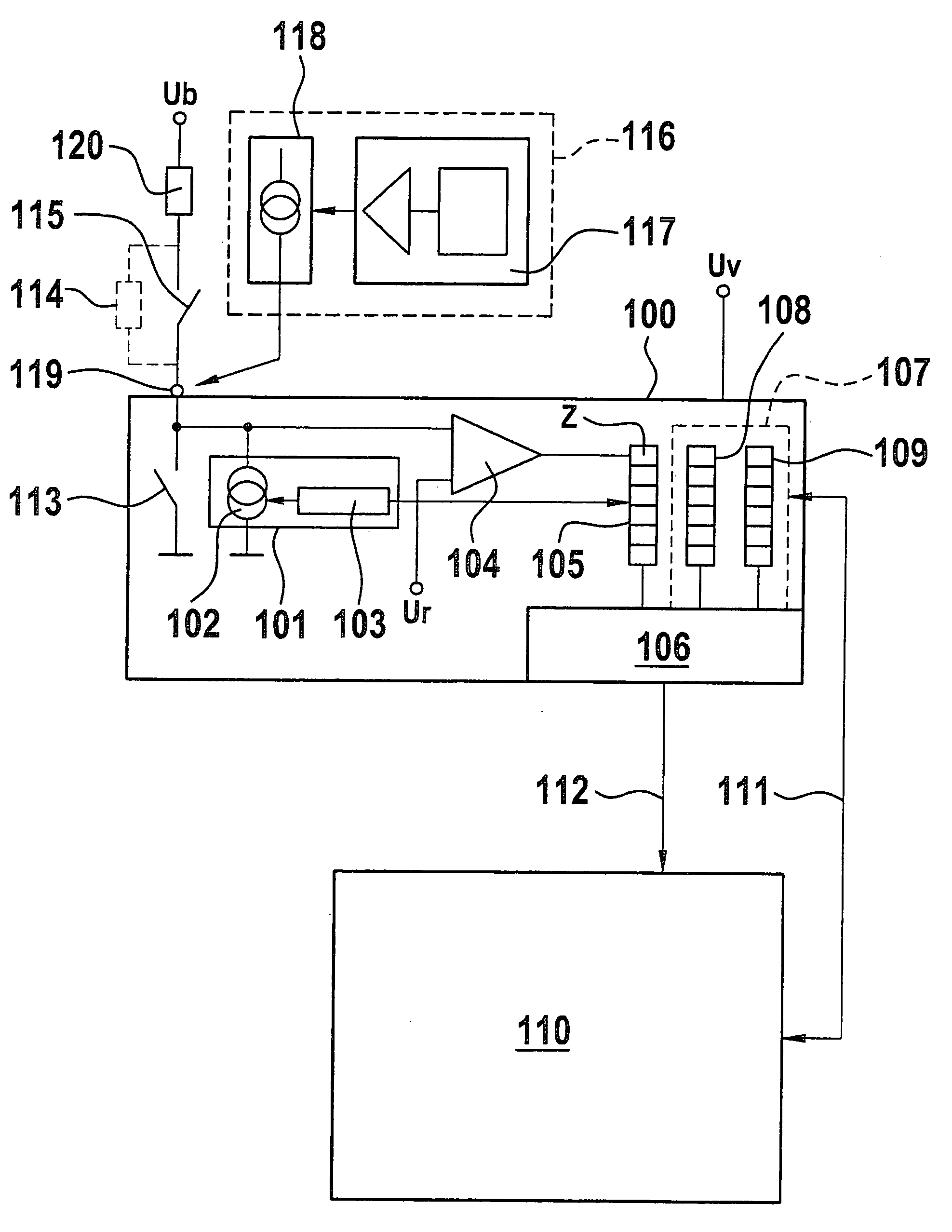
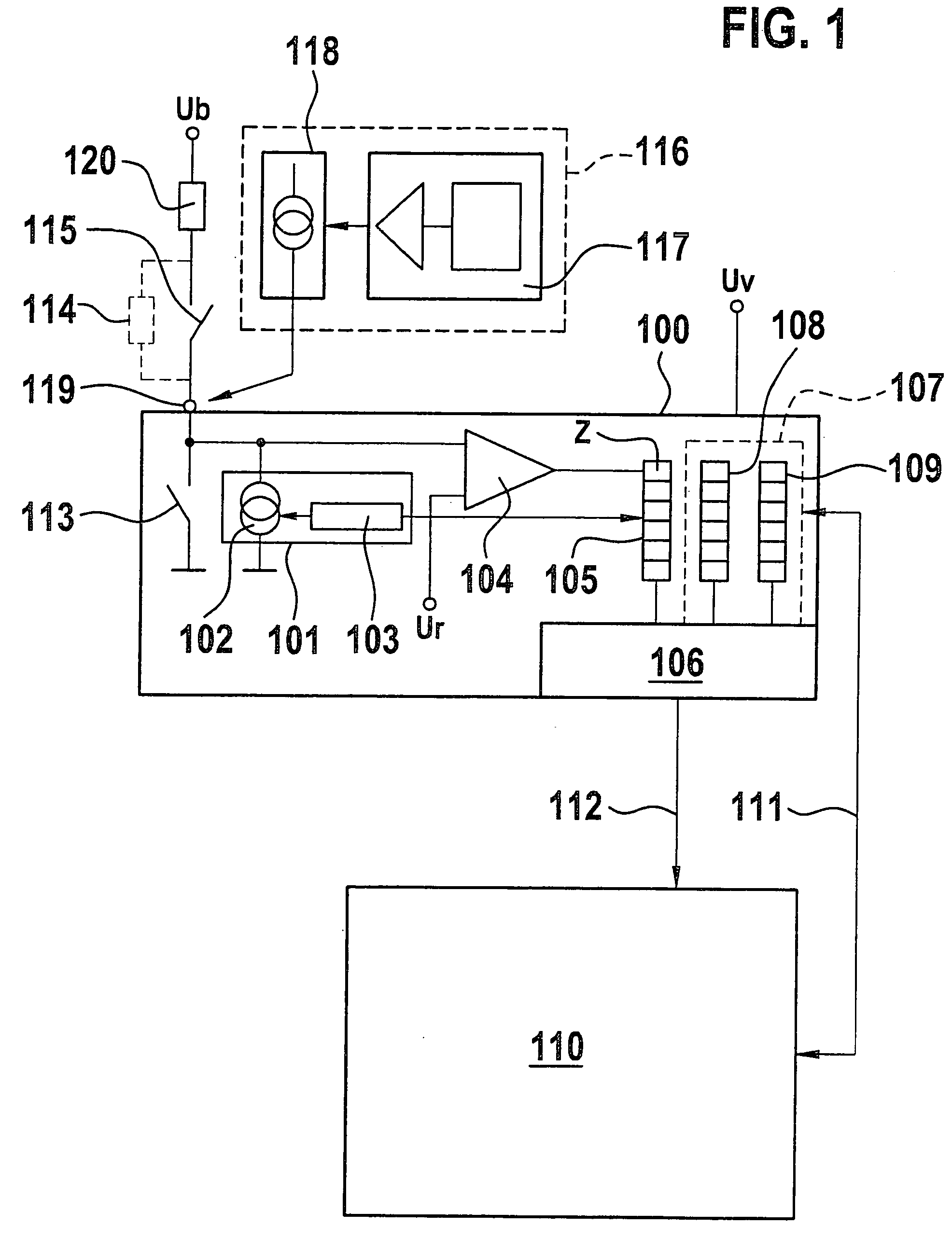
[0026]FIG. 1 shows a circuit 100 according to an example embodiment of the present invention, having a controllable energy source, in particular a current source, as well as a timing pulse means 103 combined in a clocked energy source 101. The energy source may be a voltage source, a charge source, a current source, etc.

[0027]For reasons of clarity, we speak of a current source as the preferred design case.

[0028]Clocked current source 101 is connected to a threshold value circuit element, especially a comparator 104, at whose second input there is a reference threshold Ur. Threshold value circuit element 104, on its part, is connected to a storage arrangement 105, in particular a register, for instance a shift register, whose indivi...


PUM


Abstract

A circuit and method for the input of a start signal, a controller being transferred from a first state into a second state as a function of the start signal, the energy consumption of the controller in the second state being greater than in the first state, the circuit having a clocked energy source which emits a timed energy signal, and the start signal is formed as a function of the energy signal.

Description

FIELD OF THE INVENTION[0001]The present invention relates to a circuit and a method for the input of a start signal, a controller being transferred from a first state to a second state as a function of the start signal; the energy consumption of the controller in the second state being higher than in the first state.BACKGROUND INFORMATION[0002]German Patent Application No. DE 196 45 944 A1 shows a control unit for a vehicle electrical system having at least two batteries, which are able to be loaded by a generator, and which are used for supplying various users. Information is fed to the control unit and consequently also to the microcontroller contained in it via various connections. The control unit and the microcontroller contained in it are able to output control signals via other connections. As a function of specifiable data, the vehicle electrical system control unit opens or closes the connection between the two batteries, and goes into a sleep mode after switching off. In t...

Claims


Application Information

Patent Timeline
Patent Type & Authority Patents(United States)
IPC IPC(8): G06F1/26H02J9/00H02M1/00H02M1/36
CPCH02J9/005H02M1/36Y02B70/16H02M2001/0032H03K17/18Y02B70/10H02M1/0032
Inventor HORBELT, MICHAEL
Owner ROBERT BOSCH GMBH
Why Eureka
Try Eureka