

Signal processing apparatus image processing apparatus and their methods
a technology of image processing and signal processing device, which is applied in the direction of digital computers, instruments, visual presentations, etc., can solve the problems of difficulty in perceptual the difficulty of color matching between the monitor and print image, and the inability to accurately match the color information of the image information
- Summary
- Abstract
- Description
- Claims
- Application Information
AI Technical Summary
Benefits of technology
Problems solved by technology
Method used
Image

Examples
first embodiment
[System Arrangement]
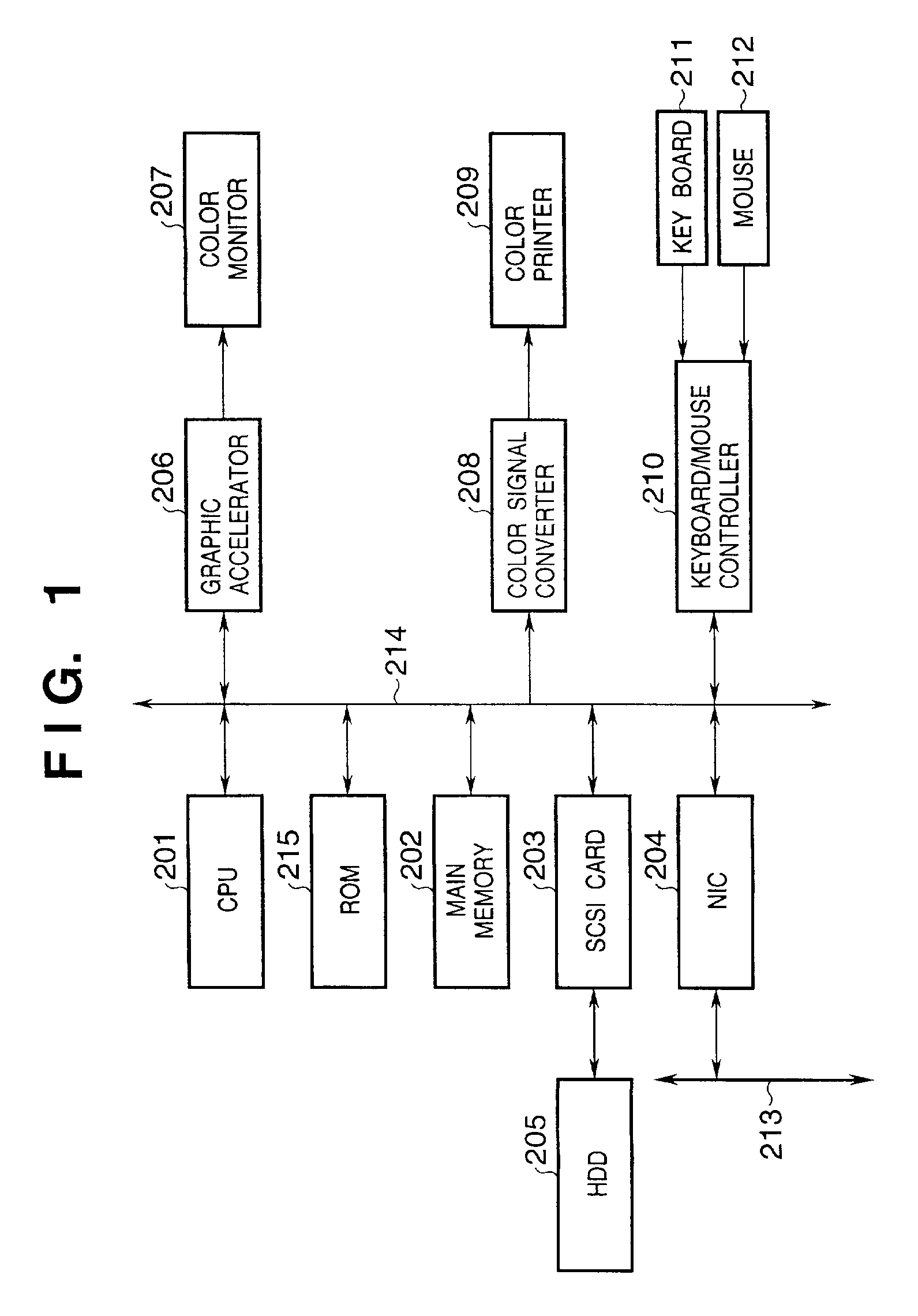
[0083]FIG. 1 is a block diagram showing the system arrangement of a color signal conversion apparatus according to the first embodiment of the present invention.
[0084]Referring to FIG. 1, reference numeral 201 denotes a microprocessor (CPU); 202, a main memory comprising a RAM or the like; 203, a Small Computer Standard Interface (SCSI) card; 204, a network interface card (NIC); 205, a hard disk drive (HDD); 206, a graphic accelerator card; 207, a color monitor such as a CRT, LCD, or the like; 208, a color signal converter with a parallel interface such as Centronics for connecting a printer; 209, a color printer; 210, a keyboard / mouse controller; 211, a keyboard; 212, a pointing device such as a mouse or the like; 213, a local area network (LAN); and 214, a Peripheral Component Interconnect (PCI) bus. Note that the CPU 201 implements various processes (to be described later) in accordance with an Operating System (OS), image processing program, and data stored i...
second embodiment
[0128]A signal processing apparatus according tot he second embodiment of the present invention will be explained below. The same reference numerals in the second embodiment denote the same parts as in the first embodiment, and a detailed description thereof will be omitted.
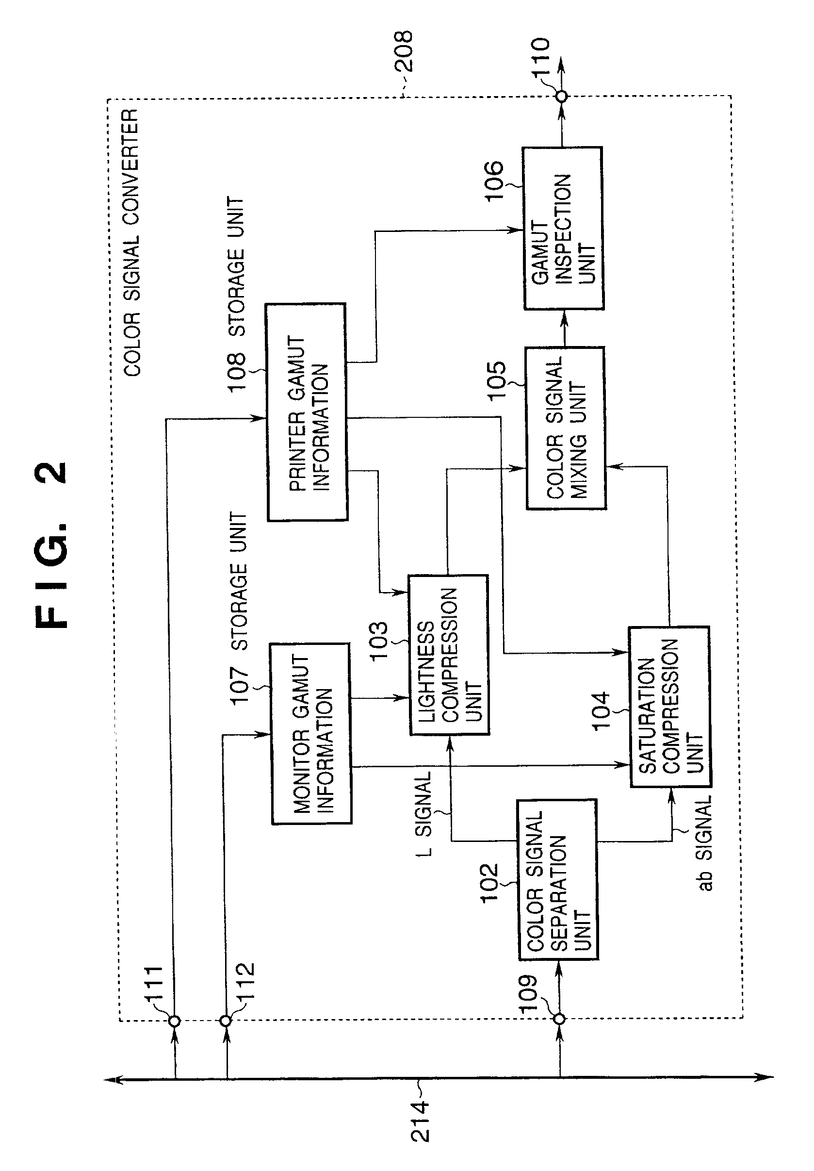
[0129]In the second embodiment, the operation of the saturation compression unit 104 in the first embodiment is modified. The saturation computing section 123 in the saturation compression unit 104 is controlled by a function g(·) that defines the input / output relationship. That is, a c signal cin input to the saturation computing section 123 and a c signal cout to be output satisfy cout=g(cin). g(·) is defined using a piecewise function consisting of n−1 segments, and is controlled to satisfy the following conditions:[0130]carrier of g(·) is [0, Cmax_monitor][0131]g(0)=0[0132]g(Cmax_monitor)=Cmax_printer[0133]g′(0)=1[0134]g′(Cmax_monitor)=γ, γ: γ>0[0135]g(mi)=mi, I: 0≦i≦n−2, mi: 0[0136]g′(mi)=1, i: 0≦i≦n−2, mi: ...
third embodiment
[0141]A signal processing apparatus according to the third embodiment of the present invention will be described below. The same reference numerals in the third embodiment denote the same parts as in the first embodiment, and a detailed description thereof will be omitted.
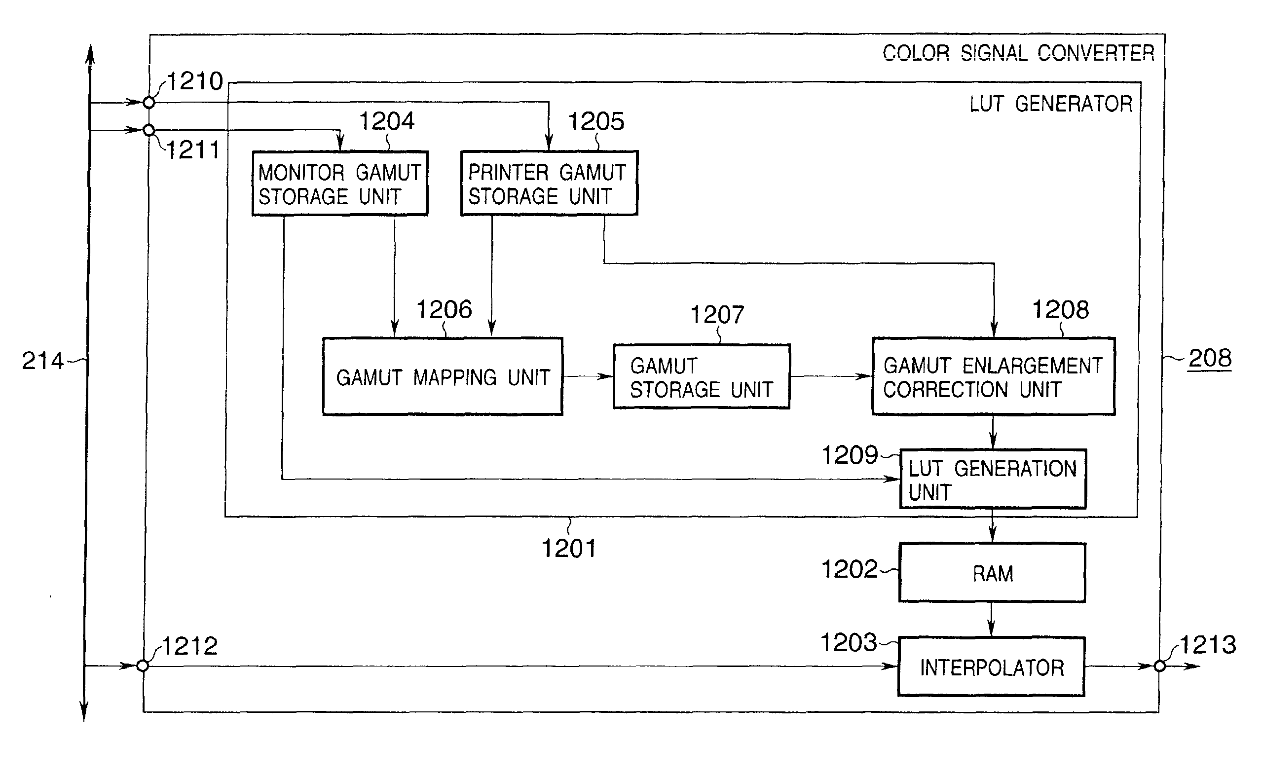
[0142]FIG. 8 is a block diagram showing the arrangement of the color signal converter 208 according to the third embodiment of the present invention.
[0143]An Lab signal of image data held in the main memory 202, i.e., a color signal in the monitor gamut as a conversion source, is input to the color signal converter 208 that converts an Lab signal in the monitor gamut into that in the printer gamut via the terminal 109. An output image to the printer, i.e., a color signal in the desired printer gamut, is output from the terminal 110.
[0144]The converter 208 receives printer gamut information from the terminal 111, and monitor gamut information from the terminal 112. The monitor gamut information is stored in the stor...
PUM
 Abstract
Description
Claims
Application Information