Defective sector determination device and optical disk drive

a technology of defective sector and determination device, which is applied in the field of buffer memory address translation, can solve the problems of data read from the optical disk medium that cannot be properly replayed even with error correction means, and the correspondence between pieces of data stored in the buffer memory is lost, etc., and achieves accurate data storage address and accurate storage

Inactive Publication Date: 2006-10-03
PANASONIC CORP
View PDF12 Cites 2 Cited by
  • Summary
  • Abstract
  • Description
  • Claims
  • Application Information

AI Technical Summary

Benefits of technology

[0014]In view of the above-described first problem, the present invention aims to provide a buffer memory address translation device, a sector address information reliability determination device, a defective sector determination device, an ECC block synchronization detection device, an optical disk drive, a medium, and program with which the correspondence between pieces of data stored in the buffer memory is not lost even if an abnormality occurs in the synchronization detection and interpolation signals due to factors such as a fingerprint or scratch.
[0015]In view of the above-described second problem, the present invention aims to provide a buffer memory address translation device, a sector address information reliability determination device, a defective sector determination device, an ECC block synchronization detection device, an optical disk drive, a medium, and program with which the correspondence between pieces of data stored in the buffer memory is not lost.
[0114]The optical disk drive according to the present invention is characterized in that a synchronization pattern and data enabling recognition of a data position included in the data read from an optical disk medium are analyzed, and the data read from the optical disk medium is accurately stored in a buffer memory.
[0115]According to the present invention, even if an abnormality in the various synchronization detection and interpolation signals is caused by factors such as a fingerprint or scratch on the optical disk medium, an accurate data storage address in the buffer memory can be generated, and when data is to be read from the optical disk medium having defective sector information recorded therein, a reliable data storage address in the buffer memory can be generated without the need for acquiring the defective sector information before reading the data from the optical disk medium.

Problems solved by technology

In the case where such an optical disk drive is used that the number of the various synchronization detection and interpolation signals corresponds to the data storage address in the buffer memory as described above, there has been a problem that the correspondence between pieces of data stored in the buffer memory is lost before and after the abnormality in the synchronization signals by an abnormality occurring in the synchronization detection and interpolation signals, such as omission or error in detection, or failed interpolation, that is caused by factors such as a fingerprint or scratch on the optical disk medium.
That is, there is a problem (first problem) that when an abnormality is caused in the synchronization detection and interpolation signals by factors such as a fingerprint or scratch on the optical disk medium, the correspondence between pieces of data stored in the buffer memory is lost.
Furthermore, there has been a problem that if the correspondence between pieces of data stored in the buffer memory is lost by the above-described factors, the data read from the optical disk medium is difficult to be properly replayed even with error correcting means.
That is, there is a problem (second problem) that if the correspondence between pieces of data stored in the buffer memory is lost by the above-described factors, the data read from the optical disk medium is difficult to be properly replayed even with error correcting means.
In addition, there has been a problem that in case of the optical disk medium having defective sector information recorded therein, there has been a problem that it is difficult to read data from the optical disk medium unless the defective sector information is acquired from the optical disk medium and the defective sector is indicated.
That is, there is a problem (third problem) that in case of the optical disk medium having defective sector information recorded therein, there has been a problem that it is difficult to read data from the optical disk medium unless the defective sector information is acquired from the optical disk medium and the defective sector is indicated.

Method used


Image

  • Defective sector determination device and optical disk drive
  • Defective sector determination device and optical disk drive
  • Defective sector determination device and optical disk drive

Examples


first embodiment

(First Embodiment)

[0260]First, a first embodiment will be described with reference to FIGS. 1, 2, 3, 4, 5, 6, 7, 8, 9, and 10.

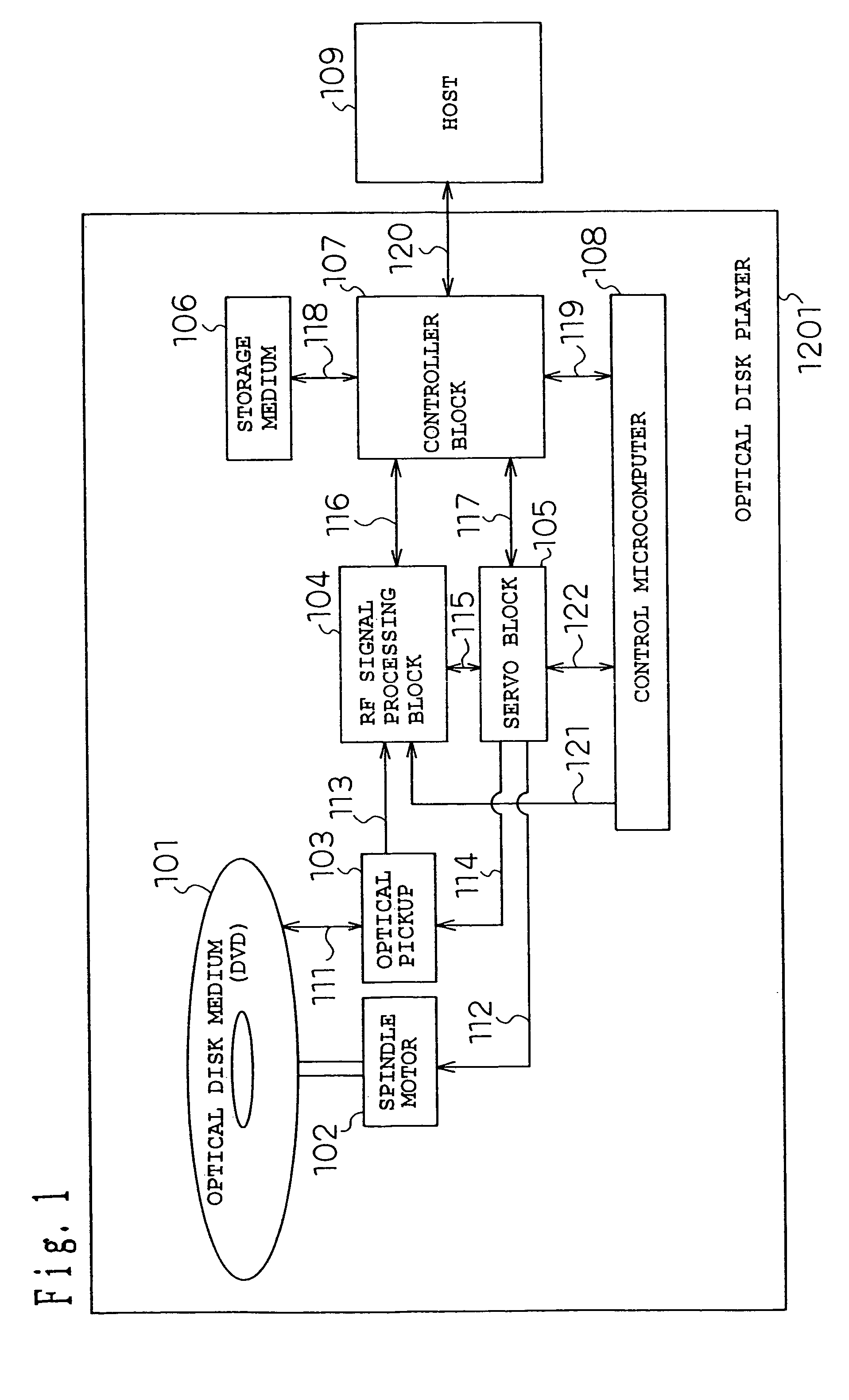
[0261]FIG. 1 shows a structure of an optical disk drive 1201 of this embodiment.

[0262]In FIG. 1, reference numeral 101 denotes an optical disk medium having information recorded therein, reference numeral 102 denotes a spindle motor for rotating the optical disk medium, reference numeral 103 denotes an optical pickup that irradiates the optical disk medium with laser light and converts the intensity of the light reflected therefrom into voltage, reference numeral 104 denotes an RF signal processing block that converts the signal converted into voltage by the optical pickup 103 into a binary signal and generates a clock synchronized with the binary signal, reference numeral 105 denotes a servo block for controlling the rotation of the spindle motor 102 and position of the optical pickup 103, reference numeral 106 denotes a buffer memory for retaining various k...

second embodiment

(Second Embodiment)

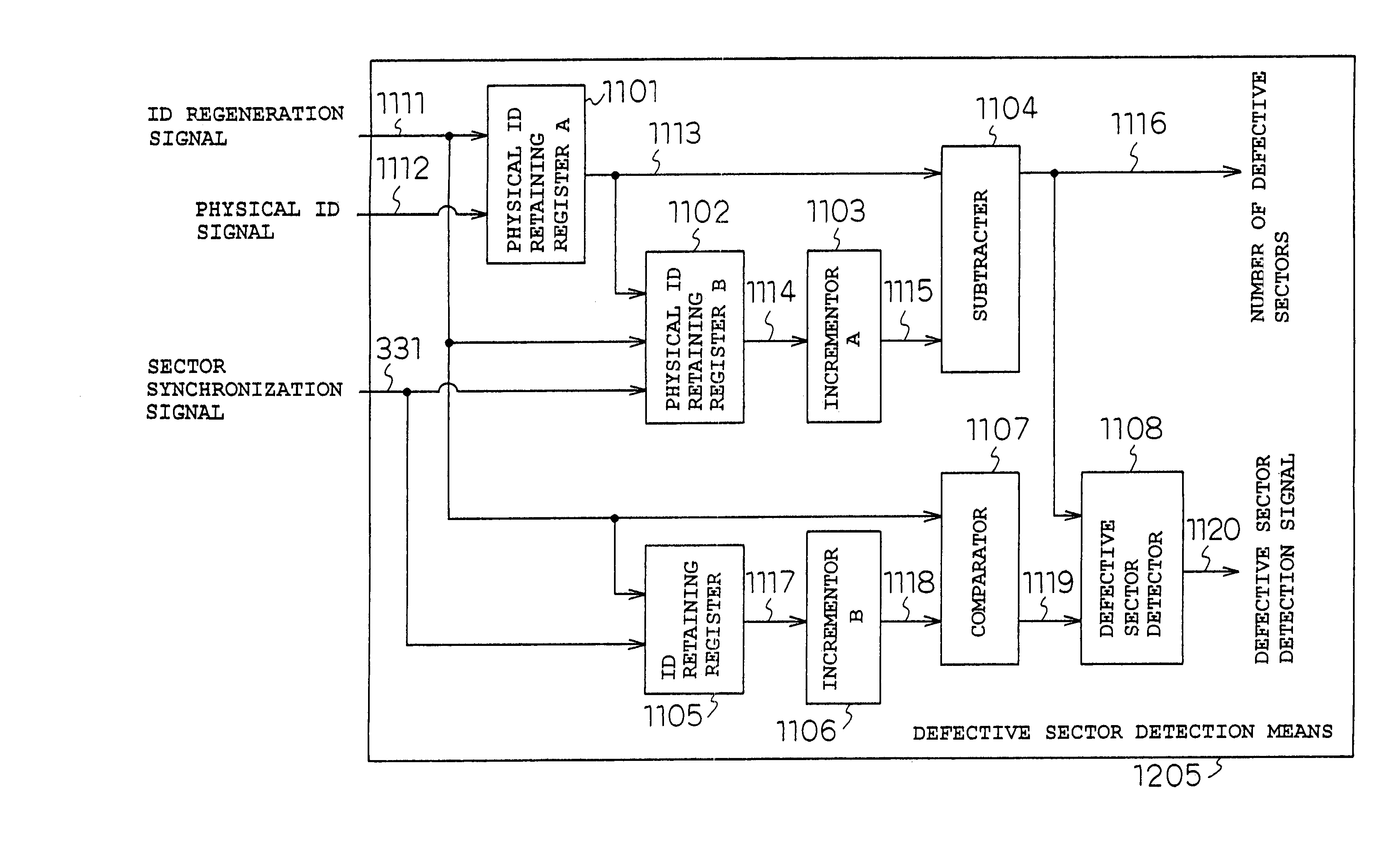
[0330]Next, a second embodiment will be described with reference to FIG. 11. FIG. 11 shows a structure of defective sector detection means 1205 of this embodiment. The same components as those in the previous embodiment are given the same reference numerals, and description thereof is omitted.

[0331]In FIG. 11, reference numeral 1101 denotes a physical ID retaining register A, reference numeral 1102 denotes a physical ID retaining register B, reference numeral 1103 denotes an incrementer A, reference numeral 1104 denotes a subtracter, reference numeral 1105 denotes an ID retaining register, reference numeral 1106 denotes an incrementer B, reference numeral 1107 denotes a comparator, and reference numeral 1108 denotes a defective sector detector.

[0332]The physical ID retaining register A 1101 monitors an error detection component of the ID information of an ID regeneration signal 1111 for each physical ID signal 1112, and if it is indicated that the acquired physica...


PUM

PropertyMeasurementUnit
physical addressaaaaaaaaaa
thresholdaaaaaaaaaa
data structureaaaaaaaaaa

Abstract

To provide an optical disk drive having an enhanced replaying capability in case of an abnormality occurring in various kinds of synchronization of the optical disk drive or in replay of a defective sector. A frame synchronization counter value address translation decoder, low order ID address translation decoder, adder / subtracter, high order ID address translation decoder, and adder are used to translate information read from an optical disk medium into an absolute storage address in a storage medium, and thus data that is highly replayed can be stored in the storage medium.

Description

[0001]This application is a divisional of U.S. patent application Ser. No. 10 / 049,207, filed Jun. 14, 2002 now U.S. Pat. No. 7,079,458, the contents of which are incorporated herein by reference, and which is a U.S. National Phase Application of PCT International Application PCT / JP2001 / 04763, filed Jun. 6, 2001.[0002]THIS APPLICATION IS A U.S. NATIONAL PHASE APPLICATION OF PCT INTERNATIONAL APPLICATION PCT / JP01 / 04763.TECHNICAL FIELD[0003]The present invention relates to a buffer memory address translation device that generates a data storage address in a buffer memory used for an error correction processing of data read from an optical disk and data transfer to a host computer, a sector address reliability determination device that processes sector address information of data read from an optical disk, a defective sector determination device that determines a defective sector of an optical disk, an ECC block synchronization detection device that detects a synchronization of ECC bloc...

Claims


Application Information

Patent Timeline
Patent Type & Authority Patents(United States)
IPC IPC(8): G11B11/03G11B20/10G11B20/12G11B20/14G11B20/18G11B27/10
CPCG11B20/10G11B20/12G11B20/18G11B20/1876G11B20/1883G11B2020/1062G11B2220/20G11B20/10527G11B20/1217G11B2020/10796G11B2020/1222G11B2220/2537G11B2020/1267G11B2020/1232G11B2020/1225G11B2020/1287
Inventor OKAZAKI, MAKOTOUEDA, YASUSHI
Owner PANASONIC CORP
Why Eureka
Try Eureka