Two-wire power transmitting/receiving device and its method

a power transmission/receiving device and two-wire technology, applied in the direction of electric controllers, data switching networks, baseband system details, etc., can solve the problems of increasing costs, limiting the transmission speed, and not allowing many power receiving side devices to be connected from the aspect of transmission efficiency, so as to reduce the processing burden of the cpu, simplify the software process of the power receiving side device, and reduce the cost of softwar

Inactive Publication Date: 2006-10-03
SEKISUI JUSHI KK
View PDF11 Cites 4 Cited by
  • Summary
  • Abstract
  • Description
  • Claims
  • Application Information

AI Technical Summary

Benefits of technology

[0019]Based on the above-described structure of the present invention, it is possible to perform time-shared transmission / reception of a power supply to the power receiving side device and communication data between the power transmitting side device and the power receiving side device. Further, it is possible for a power receiving side device to distinguish a type of data based only on level detection, by setting power levels of the transmission data from the power transmitting side device and the reply data from the power receiving side device at different levels, thereby selecting unnecessary data by a hardware-related process and reducing a processing burden of the CPU. As a result, a software process of the power receiving side device is simplified, and a cost of software can be reduced. Also, the power receiving side device can determine a timing of transmitting the reply data from the power transmitting side device, by detecting a voltage of the data reception signal, whereby it is possible to detect the timing and transmit the reply data when the power transmitting side device requests.
[0020]The above-described power receiving side data processing section is preferably characterized by selecting and receiving data having the second power level from the power transmission wire, based on the power level detection results from the power level detection section. Thus, the power receiving side device identifies the reply data from another power receiving side device by only voltage detection, and does not receive the data, thereby selecting unnecessary data by a hardware-related process and reducing a processing burden of the CPU. As a result, a software process of the power receiving side device is simplified, and a cost of software can be reduced.
[0021]The power transmitting side data processing section is preferably further characterized by attaching an address of the power receiving side device to the transmission data, as an address of a target to be instructed, and the power receiving side data processing section is characterized by processing only data having an address thereto, which is attached to the transmission data. Thus, the power transmitting side device can specify the power receiving side device processing the transmission data by attaching an address of the power receiving side device to the data to be transmitted, thereby reducing an process of the power receiving side device which does not require reception of the above-described data.

Problems solved by technology

However, the above-described high-frequency superimposition method has to use a complicated circuit structure and high-cost circuit parts for modulation in order to improve signal leakage and noise immunity, thereby increasing costs.
Also, the above-described method for performing superimposition for a phase-modulated pulse signal for power transmission has a limit in a transmission speed, and the method for causing one of DC two-wires to be interrupted or shorted out at regular intervals has a problem that there is always noise, whereby both methods do not allow many power receiving side devices to be connected from the aspect of transmission efficiencies.
Furthermore, as for the above-described method for performing time-shared power transmission for the power and the signal, a signal from the power transmitting side cannot be distinguished from a signal from the power receiving side based on a voltage, etc., and the power receiving side has to receive all signals from the power transmitting side and all signals from another power receiving side, and determine whether or not these are effective data addressed thereto, thereby complicating a process and increasing a burden in the power receiving side.
As a result, a cost of software, etc., performing a process at the power receiving side is increased.

Method used


Image

  • Two-wire power transmitting/receiving device and its method
  • Two-wire power transmitting/receiving device and its method
  • Two-wire power transmitting/receiving device and its method

Examples


Embodiment Construction

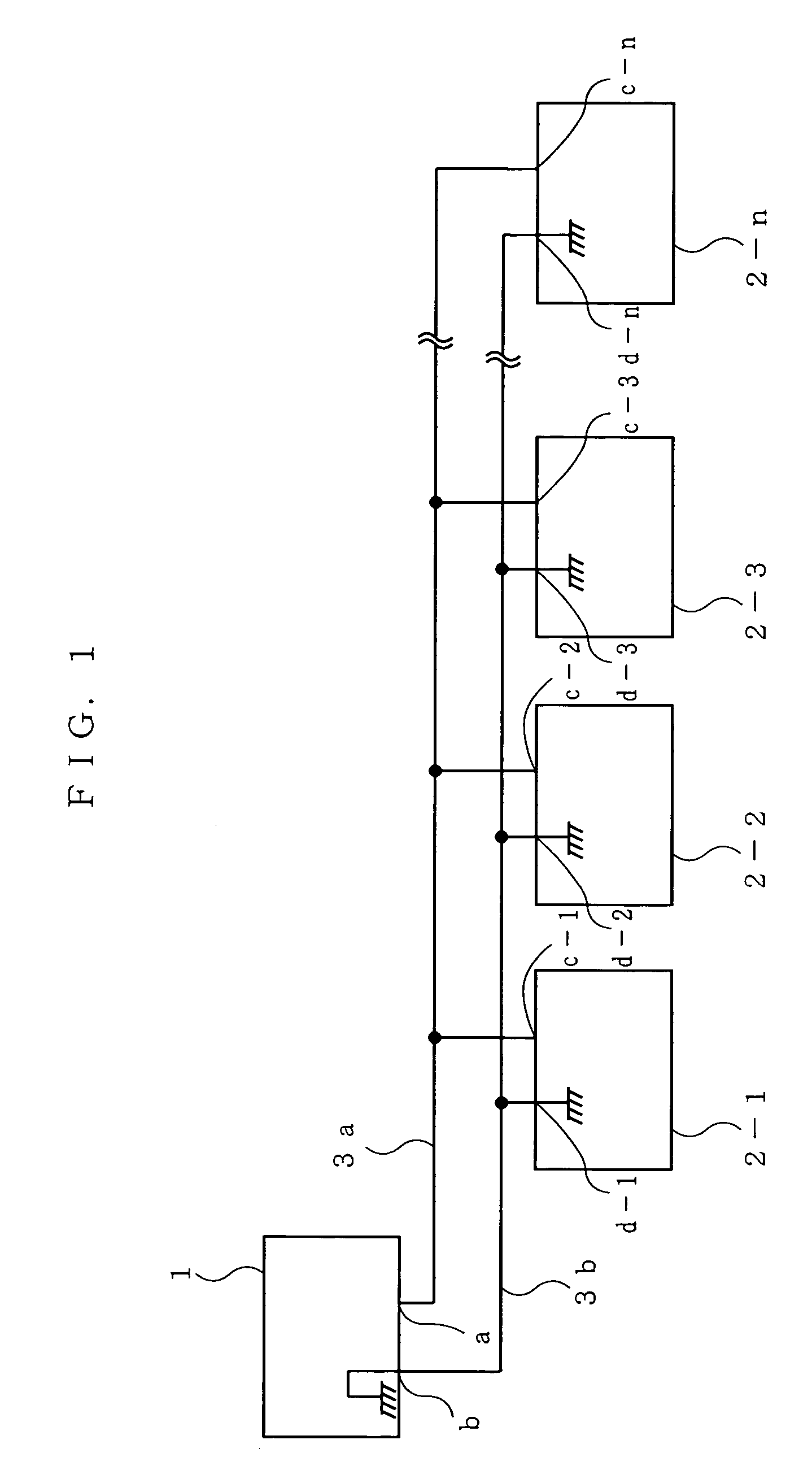
[0063]FIG. 1 is a block diagram illustrating the basic structure of a power transmitting / receiving communication apparatus according to an embodiment of the present invention. Hereinafter, using FIG. 1, the embodiment will be described.

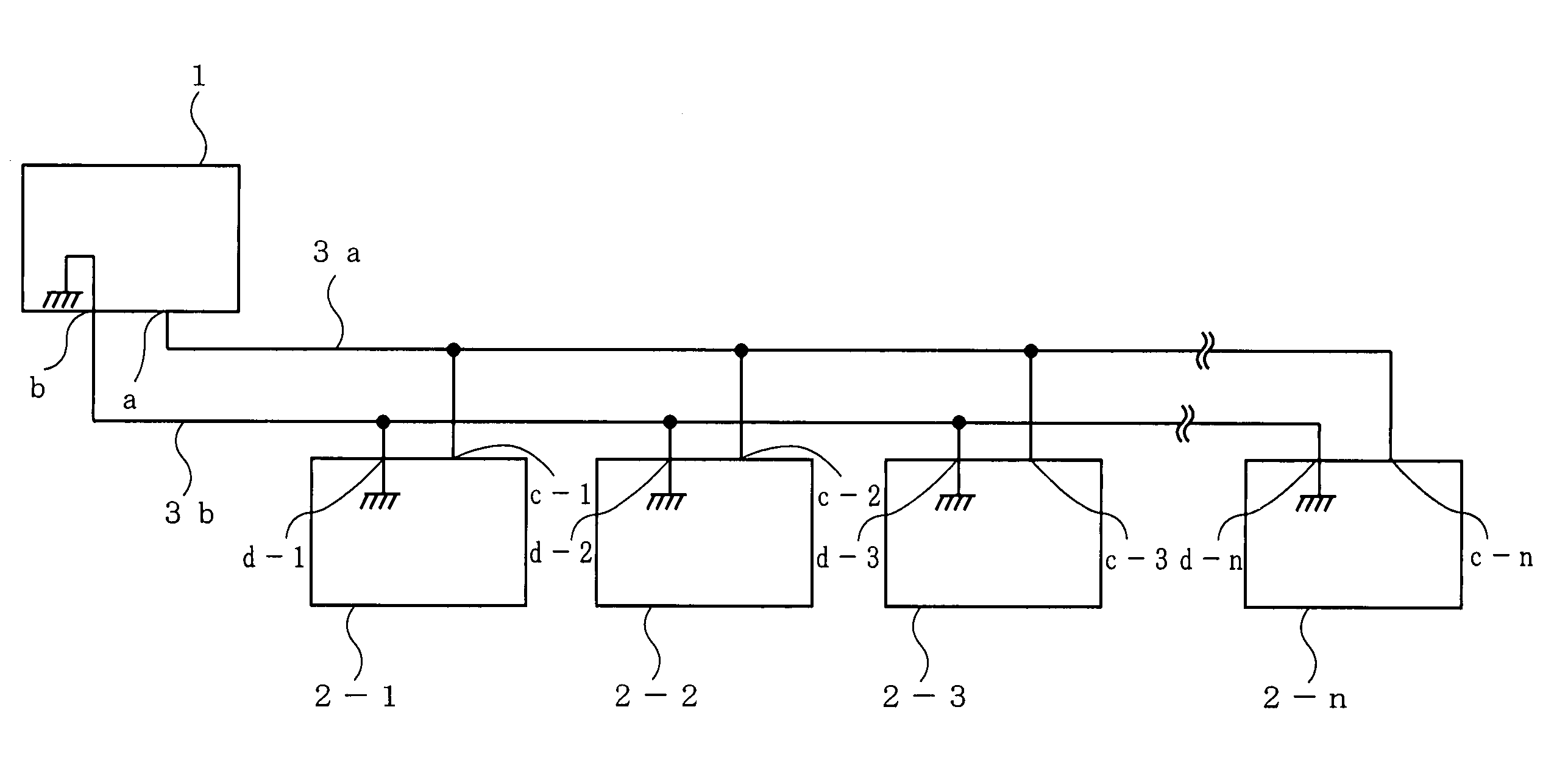
[0064]In FIG. 1, a power transmitting side device 1 and a plurality of power receiving side devices 2-1˜n are interconnected by a pair of power transmission wires 3a and 3b. The power transmission wire 3a couples a terminal a of the power transmitting side device 1 to terminals c-1˜n of the respective power receiving side devices 2-1˜n, and the power transmission wire 3b couples a terminal b of the power transmitting side device 1 to terminals d-1˜n of the respective power receiving side devices 2-1˜n. By those power transmission wires 3a and 3b, power is supplied to the power receiving side devices 2-1˜n from the power transmitting side device 1, and communication is performed between the power transmitting side device 1 and the power receiving side ...


PUM


Abstract

When power is supplied from a power transmitting side device 1, a FET 103 is turned ON and +12V direct current of a power source 101 is supplied to respective power receiving side devices. When transmission data is transmitted from the power transmitting side device 1, +5V direct current of a power source 201-1 is supplied to a terminal a, and a transistor 104 is turned ON/OFF due to a pulse-like voltage change of the transmission data, whereby the transmission data becomes a pulse-like 0V+5V output waveform, and is output to the respective power receiving side devices. When the power transmitting side device 1 receives reply data from the power receiving side device, the power receiving side device changes a voltage to a 3.5V+5V pulse as reply data. A photocoupler 105 detects the voltage change, whereby the power transmitting side device 1 receives the reply data from the power receiving side device.

Description

TECHNICAL FIELD[0001]The present invention relates to power transmitting / receiving communication methods and apparatus, and more particularly, relates to a two-wire power transmitting / receiving communication method and apparatus for performing power transmission / reception and intercommunications using two power transmission wires.BACKGROUND ART[0002]Conventionally, as a two-wire power transmission method for performing power transmission / reception and intercommunications using two power transmission wires, there is a high-frequency superimposition method for superimposing a high-frequency signal onto the transmission wires for power transmission. In the high-frequency superimposition method, a power receiving side device includes a high-frequency bandpass filter, thereby detecting only a high-frequency signal. Also, a method for superimposing a phase-modulated pulse signal onto DC two transmission wires for power transmission, and a method for causing one of DC two-wires to be inter...

Claims


Application Information

Patent Timeline
Patent Type & Authority Patents(United States)
IPC IPC(8): H04B1/20H04B3/54H04L12/40H04L25/02
CPCH04B3/548H04L12/40H04L12/40045H04L12/403H04L25/02H04B2203/547
Inventor TAZAKI, HIROOMIZUTA, YOSHINARIMIYAGAKI, MITUO
Owner SEKISUI JUSHI KK
Why Eureka
Try Eureka