Igniter for exothermic torch rod

a torch rod and exothermic technology, applied in the direction of ignitor, ammunition fuze, weapons, etc., can solve the problems of limited shelf life, unreliable or at the very least difficult to use in underwater environments, and ineffective high current and smoldering punk tube ignition systems

Active Publication Date: 2006-10-10
THE UNITED STATES OF AMERICA AS REPRESENTED BY THE SECRETARY OF THE NAVY
View PDF3 Cites 15 Cited by
  • Summary
  • Abstract
  • Description
  • Claims
  • Application Information

AI Technical Summary

Benefits of technology

[0007]Another object of the present invention is to provide a reliable, non-electric igniter adapted for use with a torch rod in underwater applications.

Problems solved by technology

However, the high current and smoldering punk tube ignition systems are either useless, unreliable or, at the very least, difficult to use in underwater environments.
However, powdered energetic compounds are not reliable and have a limited shelf life.

Method used


Image

  • Igniter for exothermic torch rod
  • Igniter for exothermic torch rod
  • Igniter for exothermic torch rod

Examples


Embodiment Construction

)

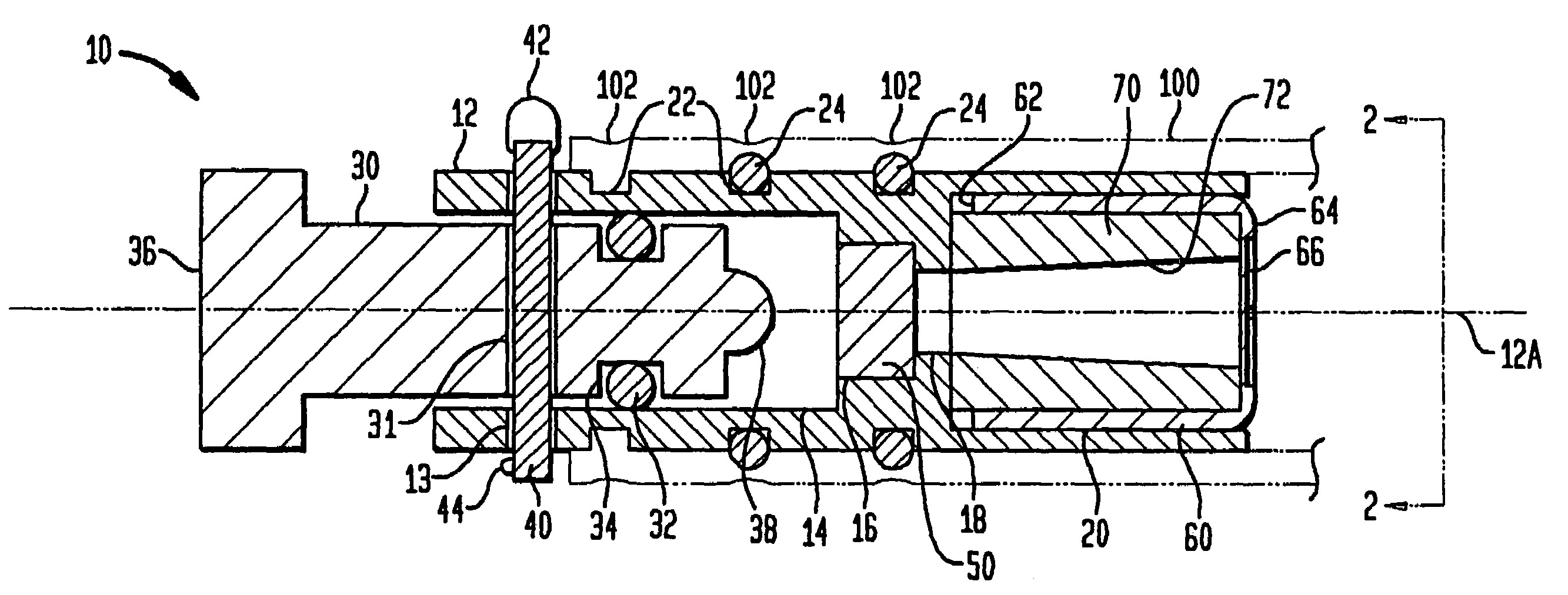
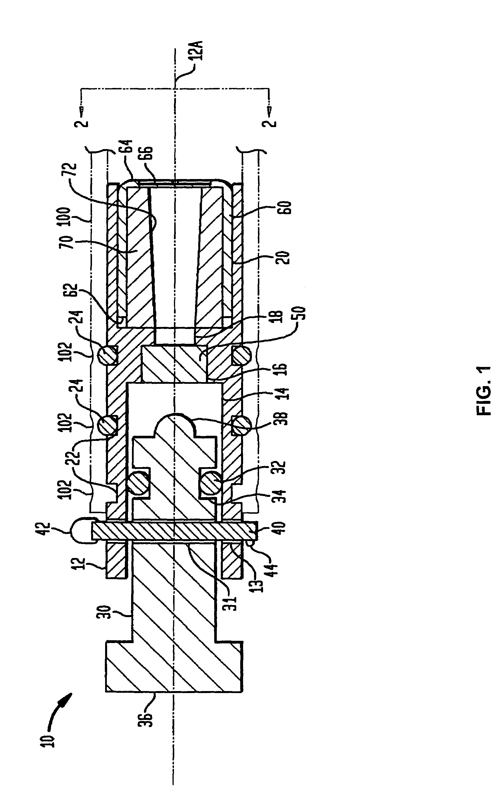
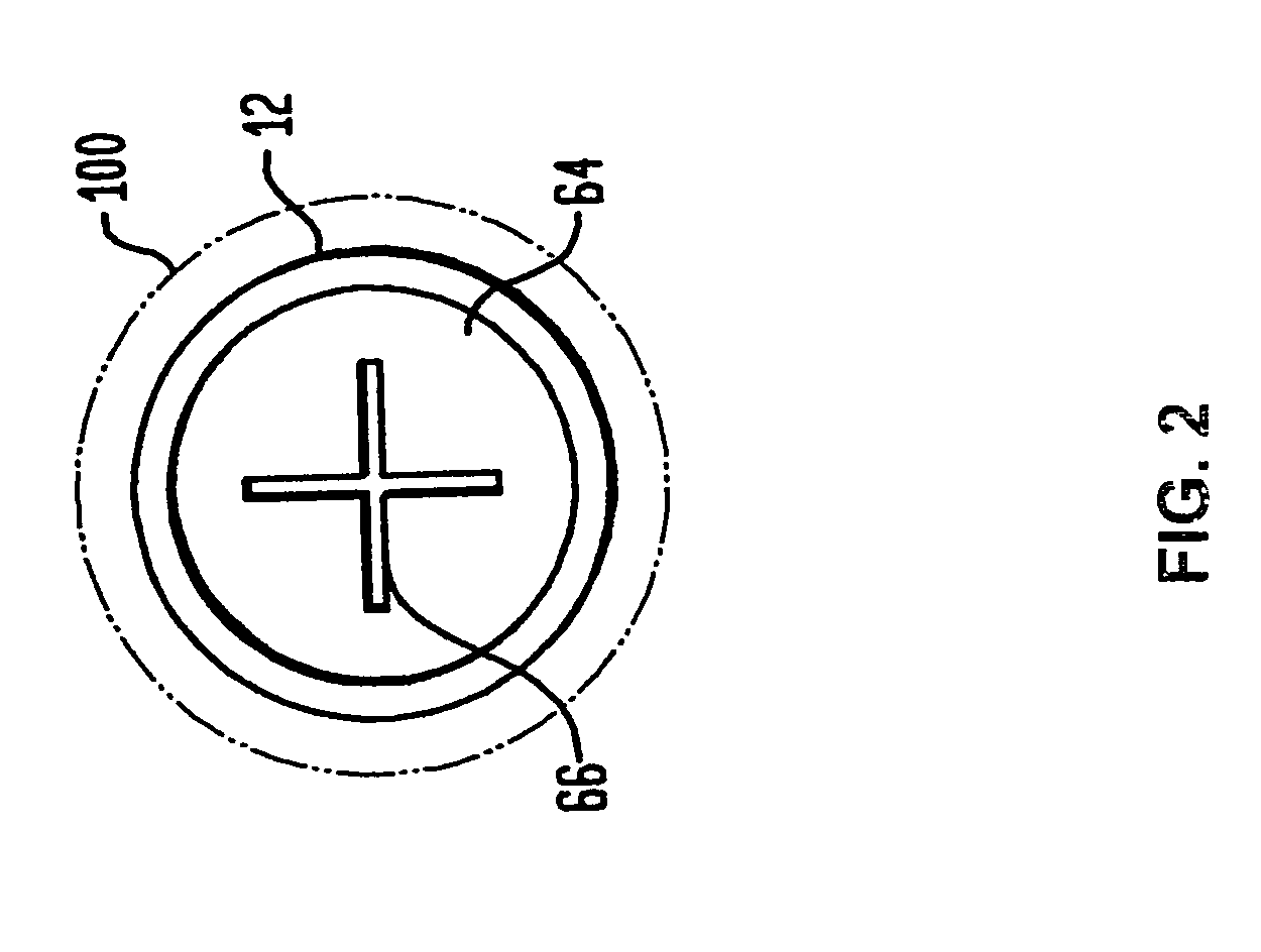
[0014]Referring now to the drawings, and more particularly to FIG. 1, an igniter in accordance with an embodiment of the present invention is shown and is referenced by numeral 10. The igniter 10 is shown installed in the aft end of a conventional torch rod 100 which is shown in phantom to indicate that torch rod 100 is not a part or limitation of the present invention. Such torch rods are well known in the art and will not be described further herein.

[0015]The igniter 10 has a rigid body or housing 12 (e.g., made of a metal such as stainless steel, a plastic, a composite, etc.) that is bored there through to define several different sized regions aligned along a central axis 12A. Typically, each bore region is cylindrical owing to the simplicity of manufacturing same in this fashion. A first bore region 14 houses a firing pin 30 (e.g., made of a metal such as stainless steel, a plastic, a composite, etc.) such that firing pin 30 can slide therein as in a piston-cylinder relationsh...


PUM

PropertyMeasurementUnit
weight percentaaaaaaaaaa

Abstract

An igniter's housing is bored continuously there through to define, in succession, several bore regions. A firing pin, slidingly fit in the first bore region, terminates in a tip that protrudes into a primer-filled second bore region when the firing pin is fully seated in the first bore region. An air-filled third bore region follows the second bore region. An open-ended cup is fitted substantially in and sealed to the fourth bore region with the cup's closed end being structurally weakened at a portion thereof. A bored out slug of pyrotechnic material is fitted in the cup.

Description

STATEMENT OF GOVERNMENT INTEREST[0001]The invention described herein may be manufactured and used by or for the Government of the United States of America for governmental purposes without the payment of any royalties thereon or therefor.BACKGROUND OF THE INVENTION[0002](1) Field of the Invention[0003]The present invention relates generally to exothermic torch rods, and more particularly to an igniter for a torch rod that does not require any power for use in or out of water.[0004](2) Description of the Prior Art[0005]As is known in the art, oxygen-based cutting-torch (or “torch rod”) systems use hollow steel tubes that house hollow or solid steel wires or rods therein. An igniter is used to ignite one end of the steel wires or rods which burn to form a cutting-torch. Current ignition methods include exposing the ends of the steel wires or rods to high current, placing the ends of the steel wires or rods in a smoldering cardboard (punk) tube, or depositing a molten metallic product ...

Claims


Application Information

Patent Timeline
Patent Type & Authority Patents(United States)
IPC IPC(8): C06C5/00
CPCC06C9/00F42B3/10F42C1/02F42C7/04F42C15/20F42C19/0803F42C19/10
Inventor BOGLE, KURT D.BRYANT, ALLEN M.D'ARCHE, STEVE P.JONES, MICHAEL H.MAKXIMENKO, VIC N.SOLTIS, FRANK L.VOIGTSCHILD, BRENT T.
Owner THE UNITED STATES OF AMERICA AS REPRESENTED BY THE SECRETARY OF THE NAVY
Why Eureka
Try Eureka