Turbine nozzle airfoil

a turbine nozzle and airfoil technology, which is applied in the direction of wind motors with parallel air flow, wind motors with perpendicular air flow, liquid fuel engine components, etc., can solve the problems of difficult to produce the turbine nozzle, improve stability, and in some cases difficult to change the sectional shape of the airfoil, so as to facilitate the redesign and prevent the flutter during operation

Active Publication Date: 2006-10-10
IHI CORP
View PDF5 Cites 11 Cited by
  • Summary
  • Abstract
  • Description
  • Claims
  • Application Information

AI Technical Summary

Benefits of technology

[0026]The present invention has been achieved in order to solve the above problems. It is an object of the invention to provide an easily redesign method for vane in order to prevent the flutter during operation of the gas turbine engine.
[0028]According to the present invention, an effect can be achieved to provide an easily redesign method for vane in order to prevent the flutter during operation of the gas turbine engine.

Problems solved by technology

Accordingly, it is difficult in some cases to change the sectional shape of the airfoil.
Therefore, some feature of the curve can not improve the stability to flutter for vane sufficiently during operation of the gas turbine engine 1 and may make it difficult to produce the turbine nozzle.

Method used


Image

  • Turbine nozzle airfoil
  • Turbine nozzle airfoil
  • Turbine nozzle airfoil

Examples


Embodiment Construction

[0035]The above and further objects and novel features of the present invention will more fully appear from the following detailed description when the same is read in conjunction with the accompanying drawings, in which:

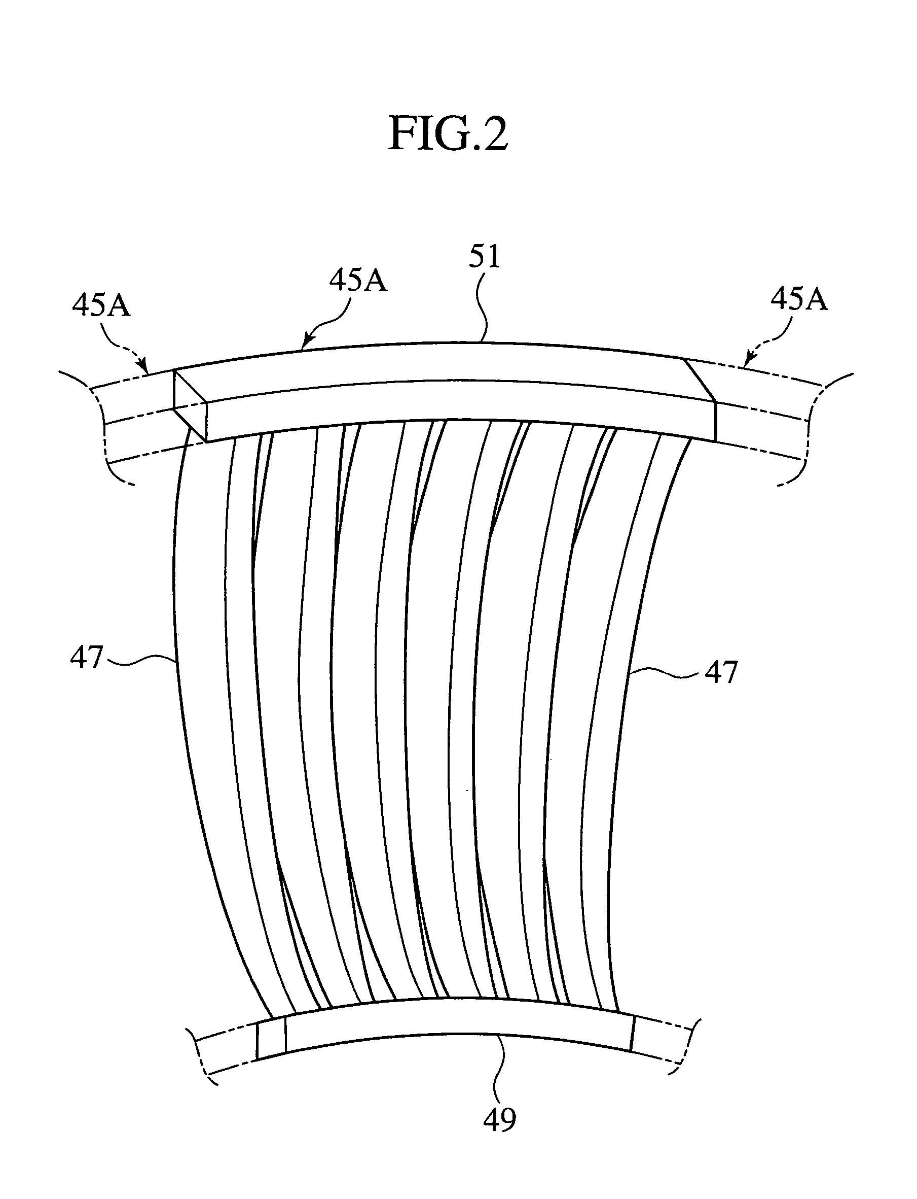
[0036]FIG. 2 is a perspective view showing a brief configuration of a turbine nozzle 45A according to an embodiment of the present invention.

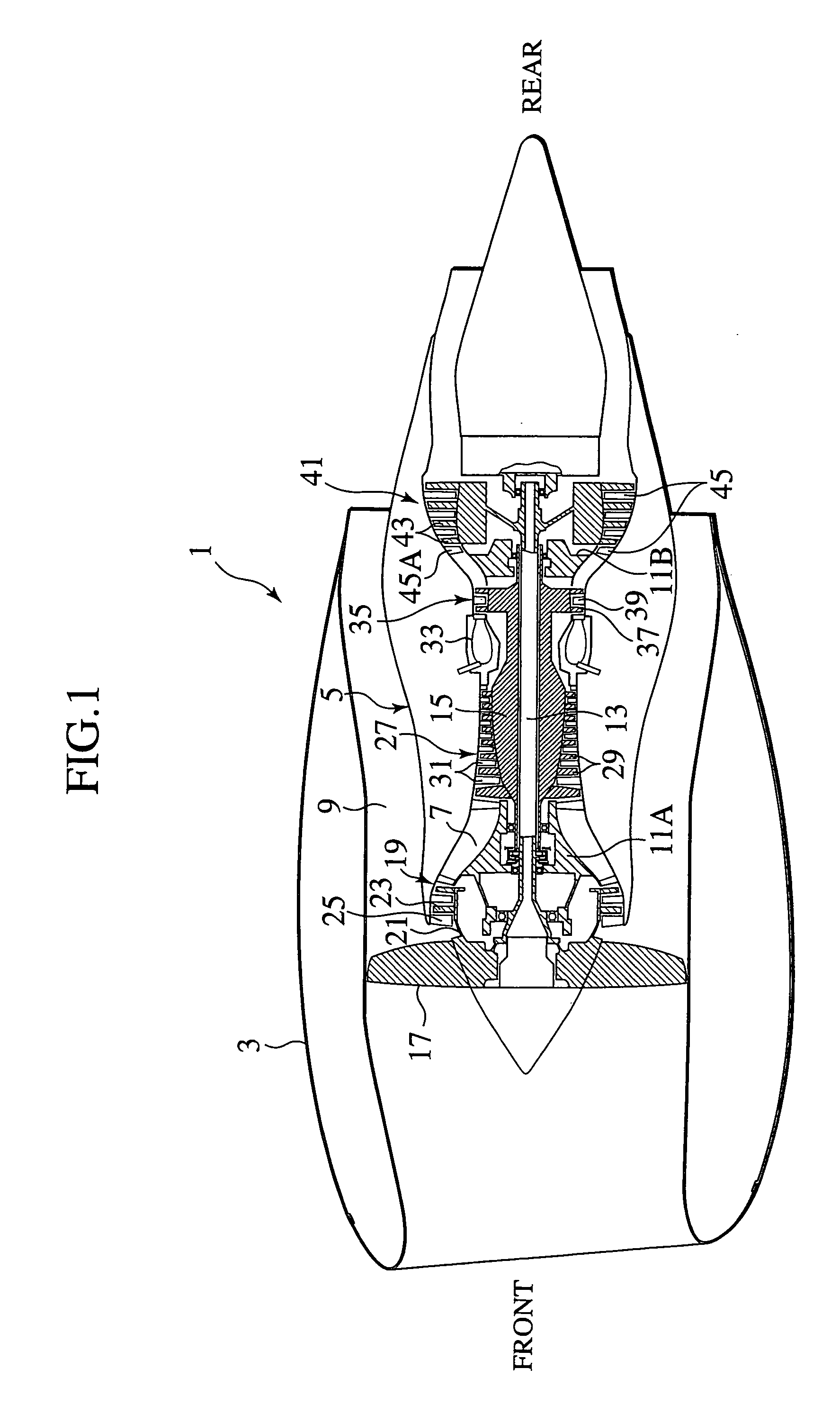
[0037]Among the turbine nozzles that construct the row of stator vane for low-pressure turbine 45 in the gas turbine engine 1 shown in FIG. 1, the turbine nozzle 45A is arranged at the most front location (close to the high-pressure turbine 35). The front side of the page of FIG. 2 almost corresponds to the front of the gas turbine engine 1, and the rear side of the page of FIG. 2 almost corresponds to the rear of the gas turbine engine 1.

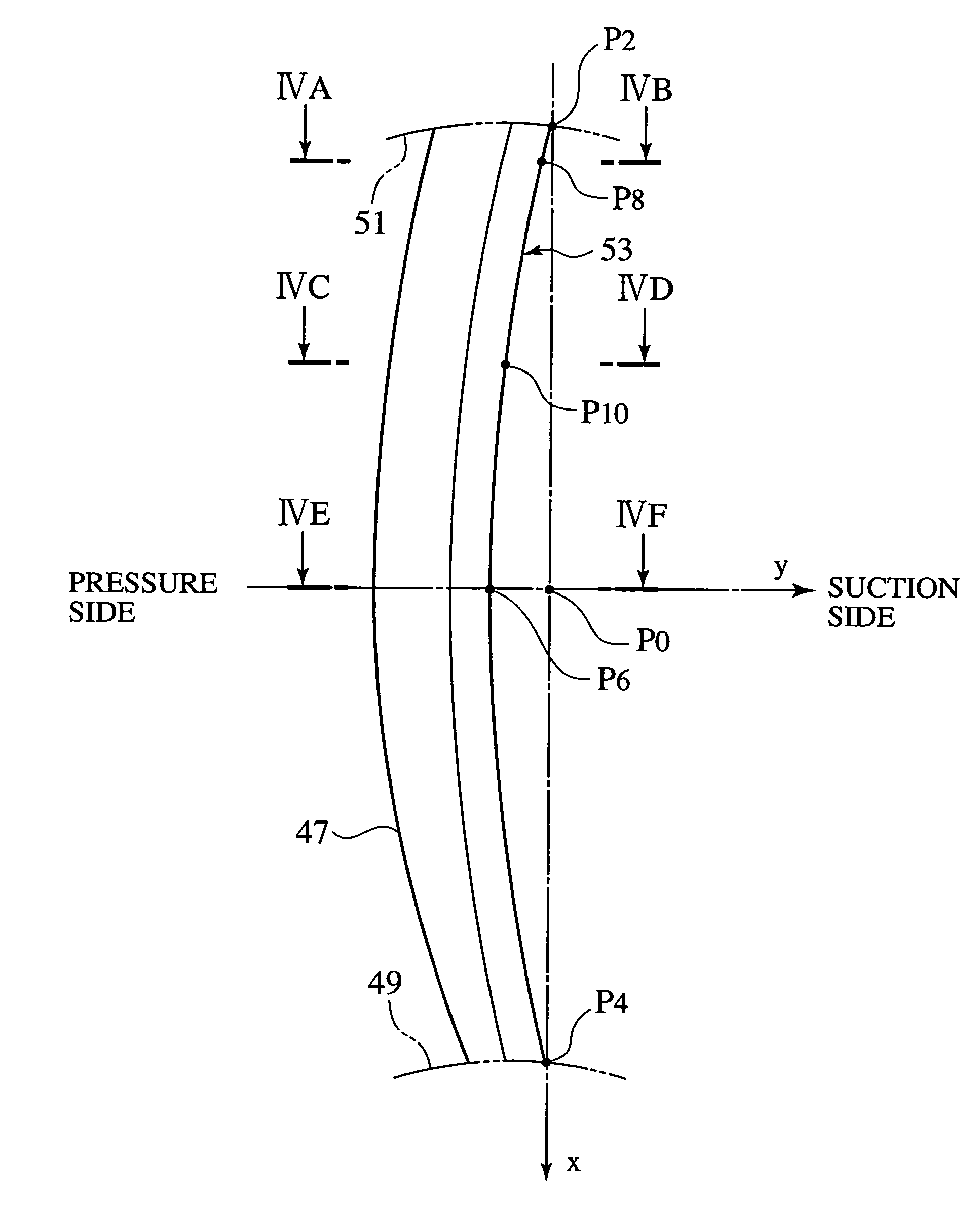
[0038]The gas turbine nozzle 45A includes a plurality of airfoil 47. Each airfoils 47 have inner band 49 and outer band 51 which are annular.

[0039]The gas turbine nozzle 45A is formed in an al...


PUM


Abstract

An easily producible turbine nozzle for a gas turbine engine is provided, which is capable of preventing flutter of the turbine nozzle during operation of the gas turbine engine. The turbine nozzle comprises airfoils stacked along the stacking axis. The high curvature portions on suction surface in airfoil section successively formed along the stacking axis of the airfoil describe a parabola line that curves toward the pressure side of the airfoil when seen from the front or rear of the turbine nozzle. The high curvature portions on suction surface in airfoil section curve most at the center along the stacking axis of the airfoil from a straight line that connects with a first intersection between the parabola line and an inner band in the turbine nozzle and with a second intersection between the parabola line and an outer band in the turbine nozzle. The maximum curvature falls within a range from 0.02 to 0.03-fold of the stacking axis of the airfoil.

Description

[0001]The present disclosure relates to subject matters contained in Japanese Patent Application No. 2003-065994, filed on Mar. 12, 2003, the disclosure of which is expressly incorporated herein by reference in its entirety.BACKGROUND OF THE INVENTION[0002]1. Field of the Invention[0003]The present invention relates to a turbine nozzle for a gas turbine engine and more particularly to a turbine nozzle having curved airfoil that describe a parabola line toward the pressure side along the airfoil stacking axis.[0004]2. Description of the Related Art[0005]A conventional or inventive turbine nozzle is employed in a gas turbine engine, which is described first with respect to its brief configuration.[0006]FIG. 1 is a cross-sectional view showing a brief configuration of a gas turbine engine 1.[0007]The gas turbine engine 1 is employed, for example, as a jet engine in an airplane. It is an engine configured to jet a high-temperature high-pressure combustion gas to provide a propelling for...

Claims


Application Information

Patent Timeline
Patent Type & Authority Patents(United States)
IPC IPC(8): F01D5/14F01D9/02F01D5/16
CPCF01D5/141F01D5/16Y02T50/673F05D2250/16Y10S416/02Y02T50/60
Inventor TSURU, ATSUSHINISHIMURA, KEIJI
Owner IHI CORP
Why Eureka
Try Eureka