Basic material for patterning and patterning method

a technology of basic materials and patterning, applied in the manufacture of electrode systems, electric discharge tubes/lamps, instruments, etc., can solve the problems of reducing the uniformity of the line width, and reducing the operating life of the inkjet head. , to achieve the effect of small level difference, low resistance, and less non-uniform line width

Inactive Publication Date: 2006-10-10
SHARP KK
View PDF16 Cites 20 Cited by
  • Summary
  • Abstract
  • Description
  • Claims
  • Application Information

AI Technical Summary

Benefits of technology

[0012]By arranging to use droplets, whose diameter is larger than a pattern width as such, the number of discharged droplets can be reduced compared with when droplets, whose diameter is equal to or smaller than a pattern width, is used.
[0038]In this case, since a pattern, which is formed by discharging droplets, becomes a wiring pattern, the wiring pattern, which has no nonuniformity of a line width and a line thickness, can be realized. Moreover, by decreasing the number of discharged droplets, the droplets do not overlap with each other on a substrate. In this way, it is possible to attain more uniform wiring thickness, that is, uniform wiring resistance. As a result, it is possible to obtain satisfactory wiring characteristics.

Problems solved by technology

When the droplets are discharged and landed on a substrate as above, there is a possibility that the droplets spread too much or come off due to the characteristics of a surface of the substrate.
Therefore, there is a problem that a desired wiring pattern cannot be obtained.
In such a case, there are problems that (i) a processing time (tact time) for a series of steps until forming the wiring patterns will increase due to an increase of the number of the droplets to discharge, and (ii) an operating life of an inkjet head will be shortened.

Method used


Image

  • Basic material for patterning and patterning method
  • Basic material for patterning and patterning method
  • Basic material for patterning and patterning method

Examples


first embodiment

[0053](First Embodiment)

[0054]One embodiment of the present invention is explained below. Note that, what is explained in the present embodiment is a pattern forming method of a gate wiring of a TFT (Thin Film Transistor) in a manufacturing process of a liquid crystal panel.

[0055]First of all, a pattern forming apparatus for realizing a pattern forming method of the present invention is explained below.

[0056]As illustrated in FIG. 5, the pattern forming apparatus according to the present invention includes a stage 12 on which a substrate 11 is to be mounted. On the stage 12, an inkjet head 13, a Y-direction driving section 14, and an X-direction driving section. 15 are provided. The inkjet head 13 is droplet discharging means for jetting out, onto the substrate 11, fluid ink (droplets) including wiring materials. The Y-direction driving section 14 moves the inkjet head 13 in a y direction, and the X-direction driving section 15 moves the inkjet head 13 move in the x direction.

[0057]...

second embodiment

[0105](Second Embodiment)

[0106]Another embodiment of the present invention is explained below. Note that, a pattern forming apparatus as shown in the first embodiment is used in the present embodiment so that it will not be explained here.

[0107]Also in the present embodiment, a gate wiring pattern forming method of TFT liquid crystal display panel is explained.

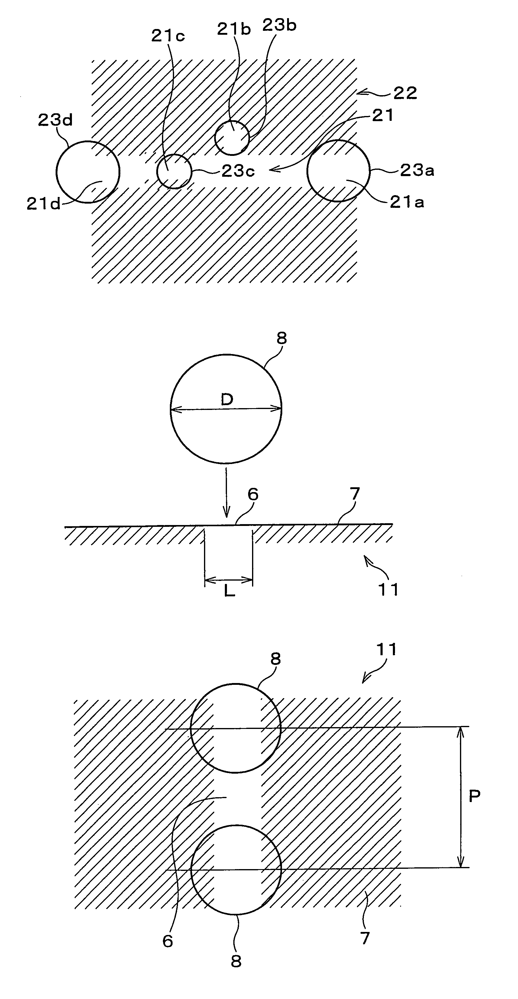
[0108]FIG. 6(a) illustrates a gate wiring pattern used in the present embodiment. In this gate wiring pattern, a water attracting / water repelling pattern is formed by a water attracting line 21 and a water repelling area 22, and the line width of the water attracting line 21 is not constant and is partially narrow. Specifically, the water attracting line 21 has a water attracting line 21a through a water attracting line 21d whose widths are respectively different. Each of the widths of the water attracting line 21b and the water attracting line 21c, which are narrower than that of the other lines, is 20 μm, and each of the wid...

third embodiment

[0115](Third Embodiment)

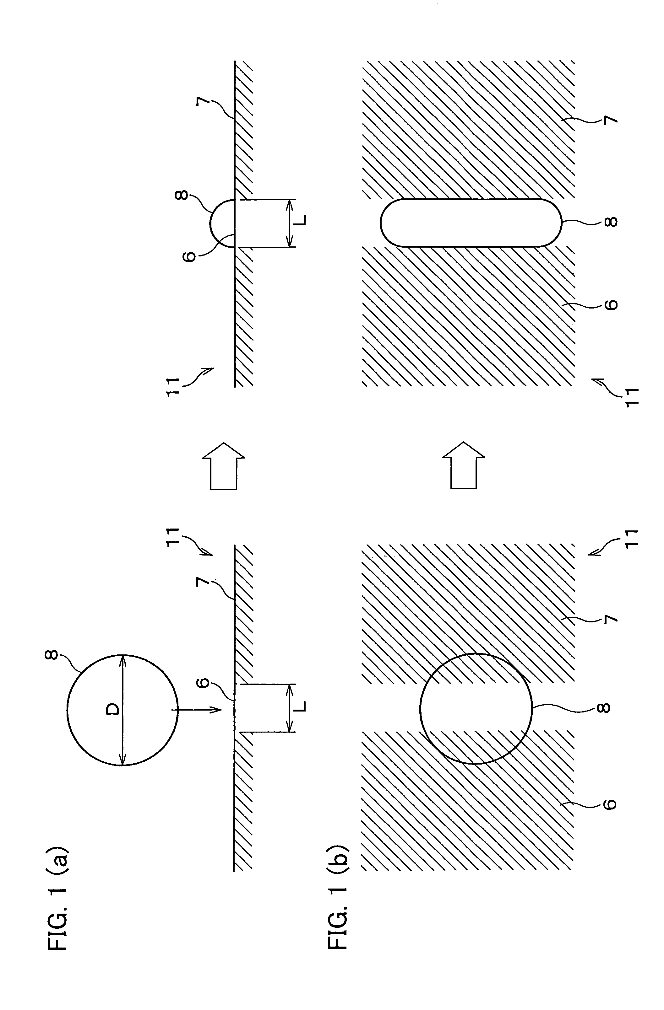
[0116]Still another embodiment of the present invention is explained below. Note that, as in the case of the first embodiment, the present embodiment discusses an example in which wiring lines are formed by using a water attracting / water repelling pattern which is formed by water attracting lines 6 and water repelling areas 7. The water attracting lines 6 and the water repelling areas 7 are formed by modifying the surface of the substrate 11 by the surface modifying processing method illustrated in FIGS. 3(a) and 3(d).

[0117]A pattern forming method in accordance with the present embodiment is a method for moving the droplet 8 to within the water attracting lines 6 as illustrated in FIG. 7(b) when the droplet 8 did not land on the center of the water attracting lines 6 on the substrate 11 as illustrated in FIG. 7(a).

[0118]The inventors found out that, when the droplet 8 landed on the substrate 11, the entire droplet 8 could move from the water repelling area 7...


PUM

PropertyMeasurementUnit
diameteraaaaaaaaaa
diameteraaaaaaaaaa
diameteraaaaaaaaaa

Abstract

A pattern forming method of the present invention includes the steps of forming, on a substrate before droplets are ejected onto the substrate, a water repelling area, in which a contact angle between the droplet and the target surface is a first contact angle, and a water attracting line, which is adjacent to the water repelling area and in which a second contact angle is smaller than the first contact angle and which is to be the pattern to be formed; and landing droplets onto the target surface such that part of the droplet landed is in a water repelling area and part of the droplet landed is in a water attracting line, the equation (1) is satisfied,D≦L×{1+2(cos θ2−cos θ1)}  (1)where D is a droplet diameter, L is a pattern width, θ1 is a first contact angle, and θ2 is a second contact angle. By decreasing the number of discharged droplets, it is possible to prevent increase of a tact time and decrease of an inkjet operating life.

Description

TECHNICAL FIELD[0001]The present invention relates to a pattern formation substrate on which a predetermined pattern is formed by discharging droplets onto a target surface, and also relates to a pattern forming method.BACKGROUND ART[0002]In recent years, a wiring pattern of a substrate is formed by an inkjet technology. A wiring pattern can be directly formed on a substrate by the inkjet technology, so that high-cost processes, such as vacuum deposition, photolithography, etching, and resist removing process, can be omitted. As a result, a substrate can be produced at low costs.[0003]Incidentally, when a wiring pattern is formed by using an inkjet head, fluid ink (droplets) containing a wiring material is jetted out and landed on a predetermined position on a substrate. When the droplets are discharged and landed on a substrate as above, there is a possibility that the droplets spread too much or come off due to the characteristics of a surface of the substrate. Therefore, there is...

Claims


Application Information

Patent Timeline
Patent Type & Authority Patents(United States)
IPC IPC(8): H01L21/302H01L21/461B41J2/01B05D1/26B41J2/14B41J2/16G02F1/1343H01J9/02H01L21/288H01L29/786H05K3/12
CPCB41J2/1433B41J2/1606H05K3/1241
Inventor HONDA, MITSURUNAKABAYASHI, TAKAYAFUJII, AKIYOSHI
Owner SHARP KK
Why Eureka
Try Eureka