Control circuit of DC-DC converter and its control method

Active Publication Date: 2006-10-10
SOCIONEXT INC
View PDF5 Cites 50 Cited by
  • Summary
  • Abstract
  • Description
  • Claims
  • Application Information

AI Technical Summary

Benefits of technology

[0009]The present invention is made to solve at least one of the problems of the background art, and it is hence an object thereof to present a control circuit of a DC—DC converter capable of being incorporated in a logic circuit, by having a digital error amplifier capable of controlling the gain depending on an input voltage and output voltage, that is, controlling the gain dynamically, and eliminating a resistance or a capacitor of high precision used in a feedback circuit or a gain setting.
[0018]In the digital error amplifier, hence, it is not necessary to determine the gain of the differential voltage amplifier preliminarily by the relation of the input voltage and the output voltage. As a result, a resistance or a capacitor of high precision used in the feedback circuit or the gain setting is not needed, and the control circuit of the DC—DC converter of the present invention can be built in the logic circuit, so that a logic LSI capable of operating efficiently at an arbitrary supply voltage can be constructed.

Problems solved by technology

Such a resistance or a capacitor cannot be built in a semiconductor circuit, and a control circuit of a DC—DC converter cannot be incorporated in the logic circuit.
As a result, there is a problem in that LSI capable of operating efficiently at an arbitrary supply voltage cannot be constructed.
However, if the error amplification of an output voltage and a reference voltage of the DC—DC converter is merely digitized, the gain setting in consideration of relation of an input voltage and an output voltage is required.
As a result, there are problems in that a large scale circuit is needed for the gain setting or a DSP processing circuit and the circuit scale is increased, or a consumption current is increased.

Method used


Image

  • Control circuit of DC-DC converter and its control method
  • Control circuit of DC-DC converter and its control method
  • Control circuit of DC-DC converter and its control method

Examples


Embodiment Construction

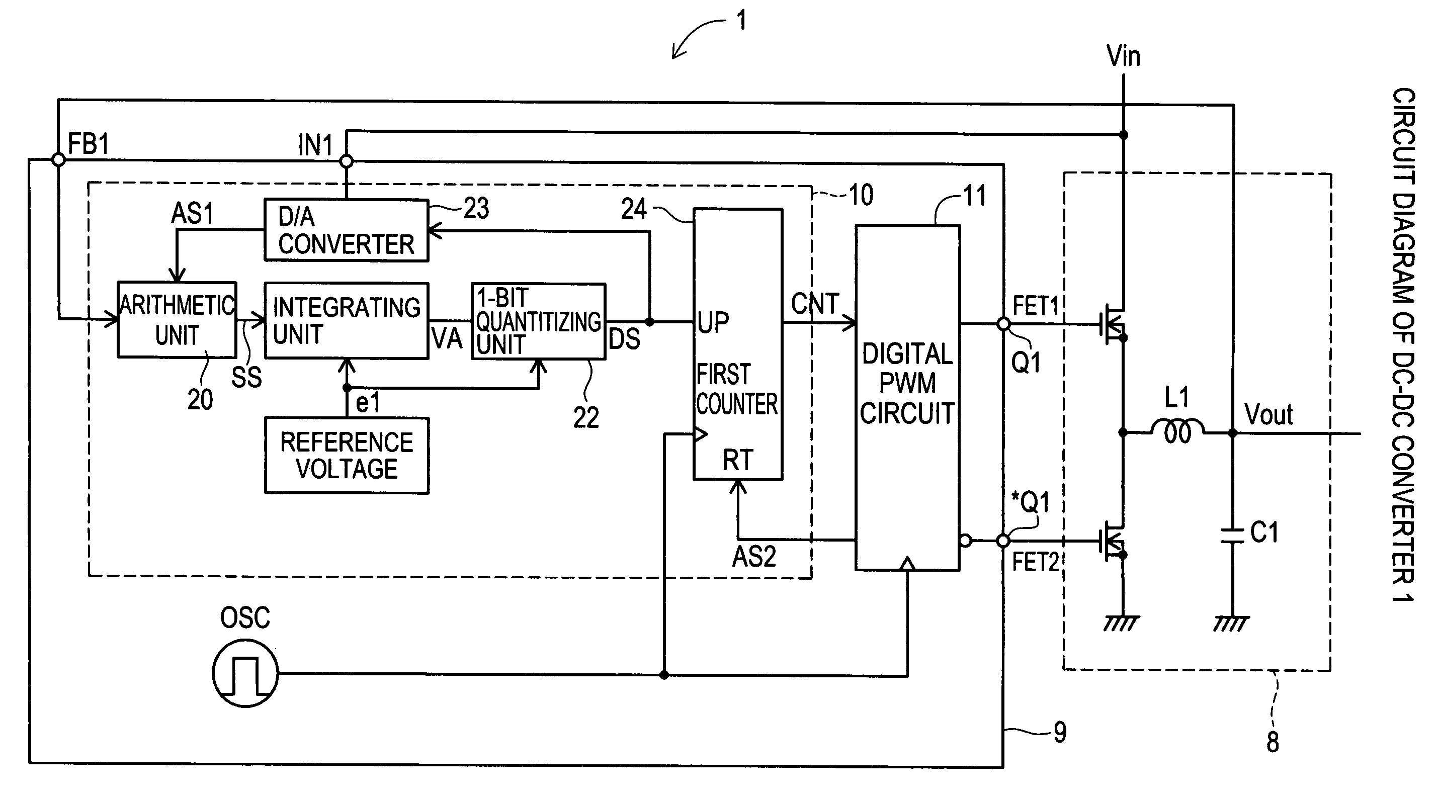
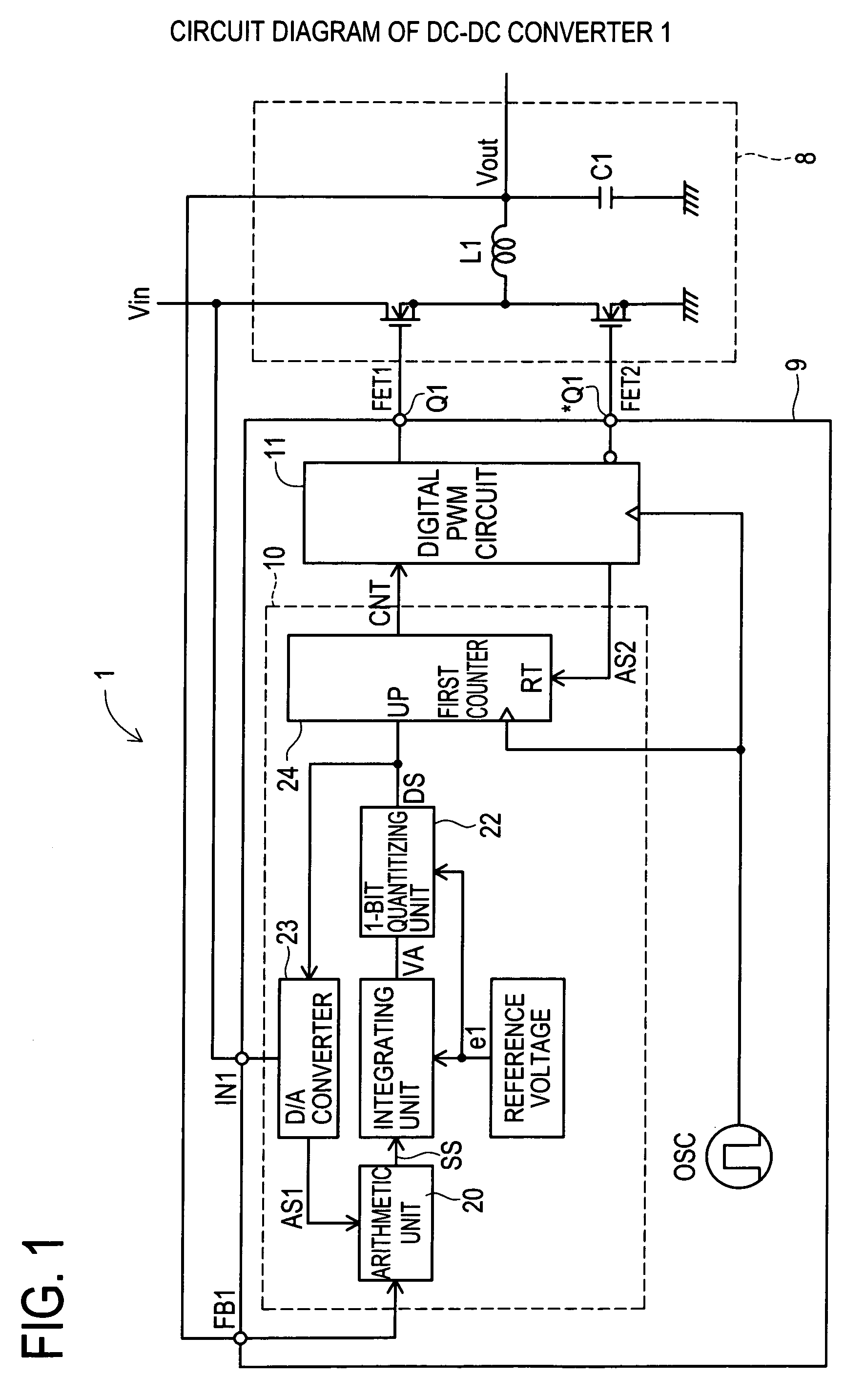
[0028]A specific embodiment of a control circuit of a DC—DC converter having a digital error amplifier of the invention is specifically described below while referring to FIG. 1 to FIG. 6. First, in FIG. 6, a DC—DC converter 100 of a synchronous rectifying switching type having an analog error amplifier is explained. An output voltage Vout of the DC—DC converter is input to a terminal FB1 of a control unit 109. Between the terminal FB1 and a grounding voltage Vss, a resistance R1 and a resistance R2 are connected in series, to divide an output voltage Vout is divided. A reference voltage e1 is input to a non-inverting input of an error amplifier ERA1, and a divided voltage of an output voltage Vout is input to an inverting input. Between the inverting input terminal and an output terminal of the error amplifier ERA1, a resistance R3 and a capacitor C2 are connected as a feedback circuit. A series impedance of the resistance R3 and the capacitor C2 is a feedback resistance Z. An outp...


PUM


Abstract

To present a control circuit of a DC—DC converter to be incorporated in a logic circuit, having a digital error amplifier capable of controlling the gain depending on an input voltage and an output voltage, without requiring a resistance or a capacitor of high precision used in a feedback circuit or the like. A ΣΔ AD converter type error amplifier 10 includes an arithmetic unit 20, an integrating unit 21, a 1-bit quantizing unit 22, a D / A converter 23, and a first counter 24. The arithmetic unit 20 outputs a differential signal of an output voltage Vout and an average output voltage AV. The integrating unit 21 outputs an integral signal by integrating the differential signal. The 1-bit quantizing unit 22 outputs a 1-bit digital signal by quantizing the integral signal. The D / A converter 23 converts from digital to analog depending on a 1-bit digital signal. A digital PWM circuit 11 determines the on-duty of the main switching element of the DC—DC converter depending on the pulse density of the D / A converter 23.

Description

CROSS-REFERENCE TO RELATED APPLICATIONS[0001]This application is based upon and claims the benefit of priority from each of the prior Japanese Patent Application No. 2005-247554 filed on Aug. 29, 2005, the entire contents of which are incorporated herein by reference.BACKGROUND OF THE INVENTION[0002]1. Field of the Invention[0003]The present invention relates to control of a DC—DC converter, and more particularly to a control circuit and its control method of a DC—DC converter which can be composed easily in a logic circuit.[0004]2. Description of the Related Art[0005]In a control circuit for a DC—DC converter of synchronous rectifying switching type having an analog error amplifier, the analog error amplifier has a resistance or a capacitor as a feedback circuit. In the event of fluctuations of an input voltage of a DC—DC converter, or variable control of an output voltage of a DC—DC converter, the error amplifier is required not to oscillate. In order to set a gain to have an allo...

Claims


Application Information

Patent Timeline
IPC IPC(8): G05F1/40
CPCH02M3/157H02M2001/0022H03M3/43H03M3/456H03M3/506H02M1/0022H02M3/155
Inventor YOSHINO, TAKAHIRO
Owner SOCIONEXT INC
Why Eureka
Try Eureka