
Storage device including a center tapped write transducer

a technology of write transducer and storage device, which is applied in the direction of mounting head within the housing, functional testing of recording head, instruments, etc., can solve the problems of head damage, permanent damage to the head, and damage to the head, and can also occur by mechanical abrasion

Inactive Publication Date: 2006-10-10
WESTERN DIGITAL TECH INC
View PDF7 Cites 130 Cited by
  • Summary
  • Abstract
  • Description
  • Claims
  • Application Information

AI Technical Summary

Benefits of technology

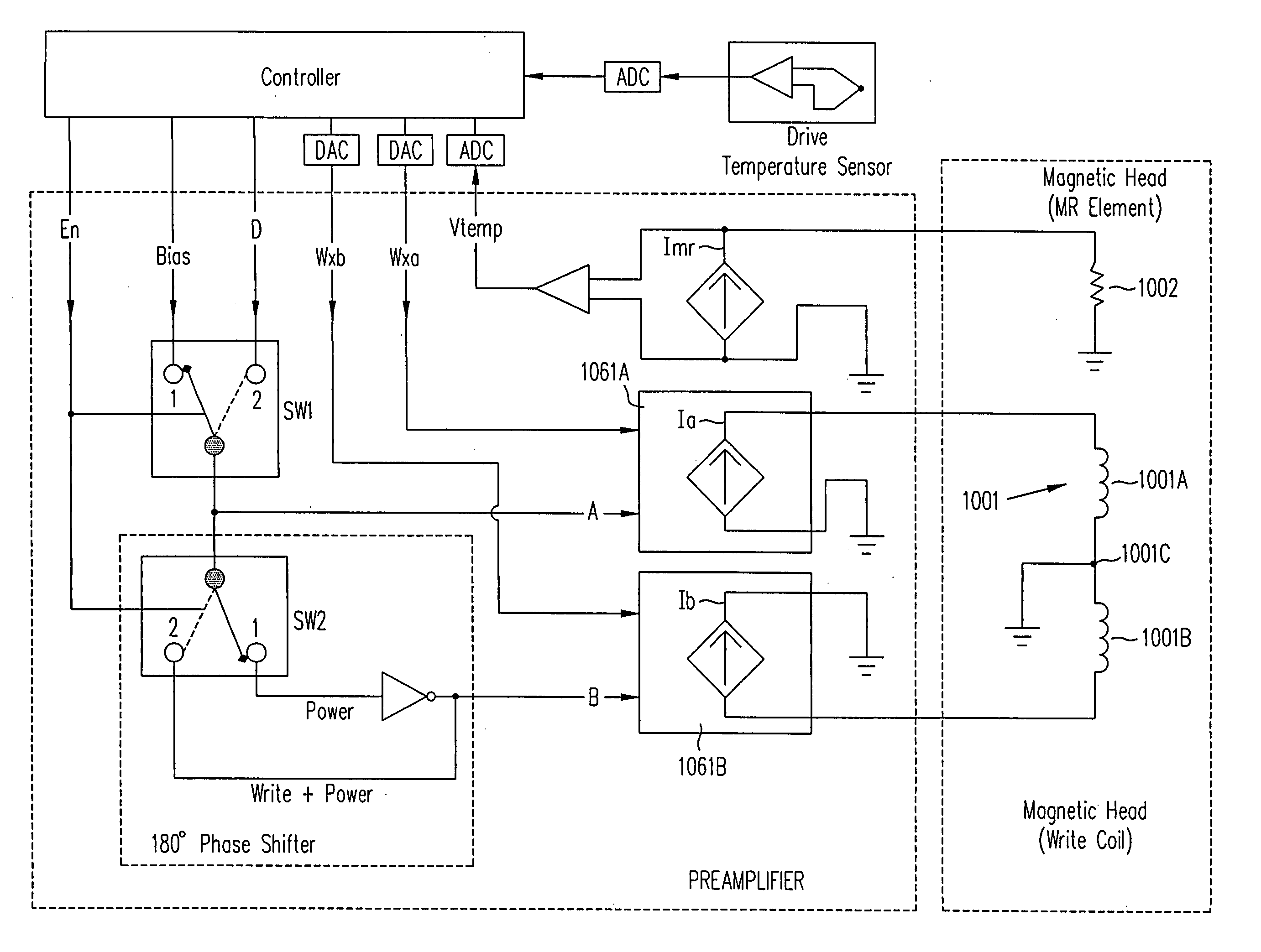
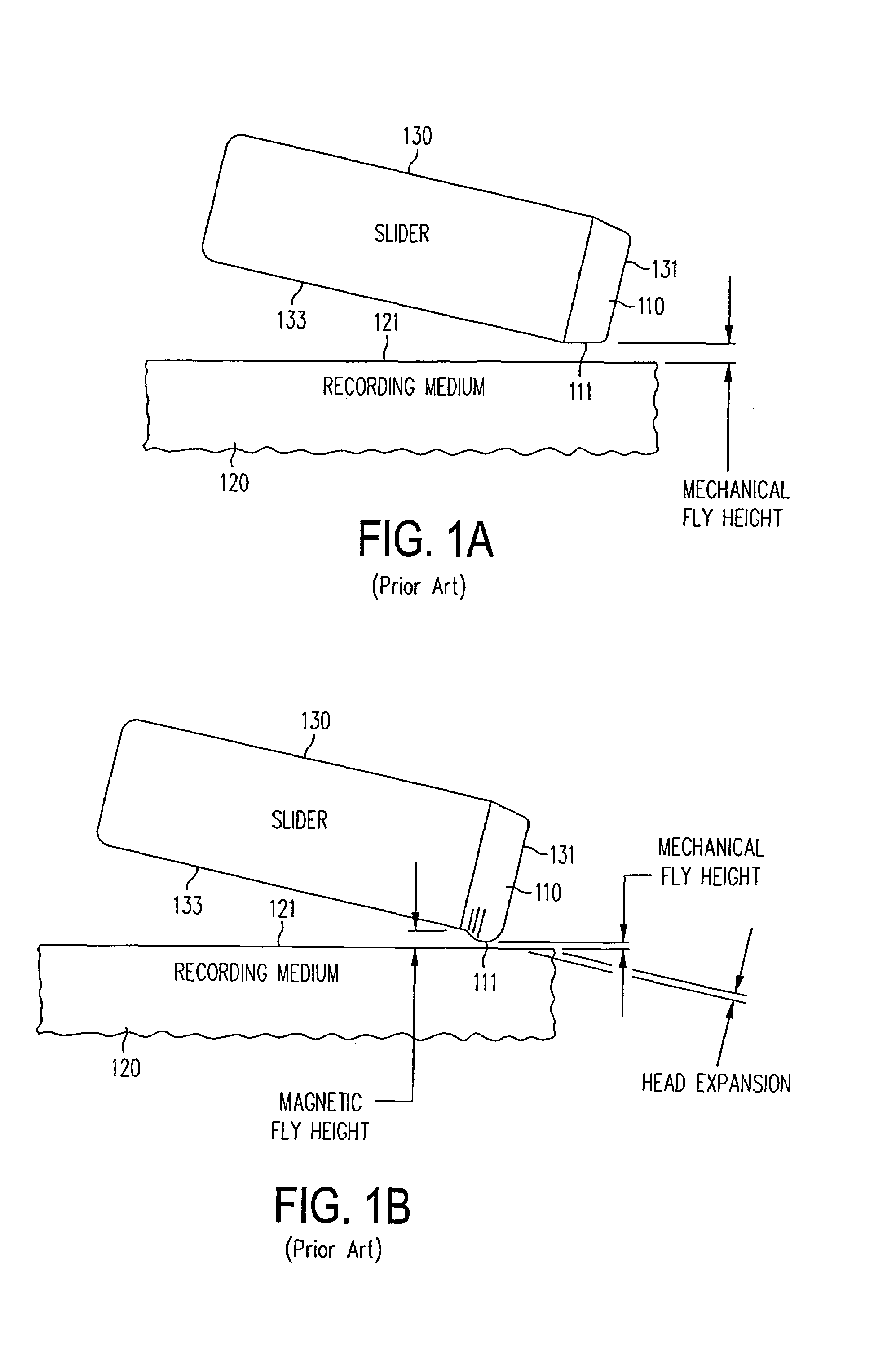
[0009]A head for use in a drive in accordance with the invention includes a heating element capable of generating heat sufficient to cause the head to have a shape that is similar or identical to the shape that the head has when performing an operation (e.g. writing) on a recording medium in the drive. The heating element is activated in accordance with the invention when the operation is not being performed. Hence, in some embodiments of the invention, a head generates the same amount (or similar amount) of heat and is therefore at the same temperature (also called “operating temperature”), regardless of whether or not an operation (such as writing) is being performed. Therefore, the head maintains a fixed shape or has a shape that varies minimally, within a predetermined range around the fixed shape, that in turn results in maintaining fly height (distance between the head and the recording medium).

Problems solved by technology

The reduction in fly height is sufficient to cause the head to come into contact with the medium, resulting in the head itself or the recording medium or both being damaged.
When such a current surge happens, read / write circuitry in the head may melt, thereby damaging the head permanently.
Damage to the head can also occur by mechanical abrasion, e.g. when a head's protrusion acts as a phonograph needle.
Contact of a head with the medium may also affect the drive's servo control (PES, position error signal), resulting in the head becoming unable to track the medium so that data cannot be written or read.

Method used


Image

  • Storage device including a center tapped write transducer
  • Storage device including a center tapped write transducer
  • Storage device including a center tapped write transducer

Examples


Embodiment Construction

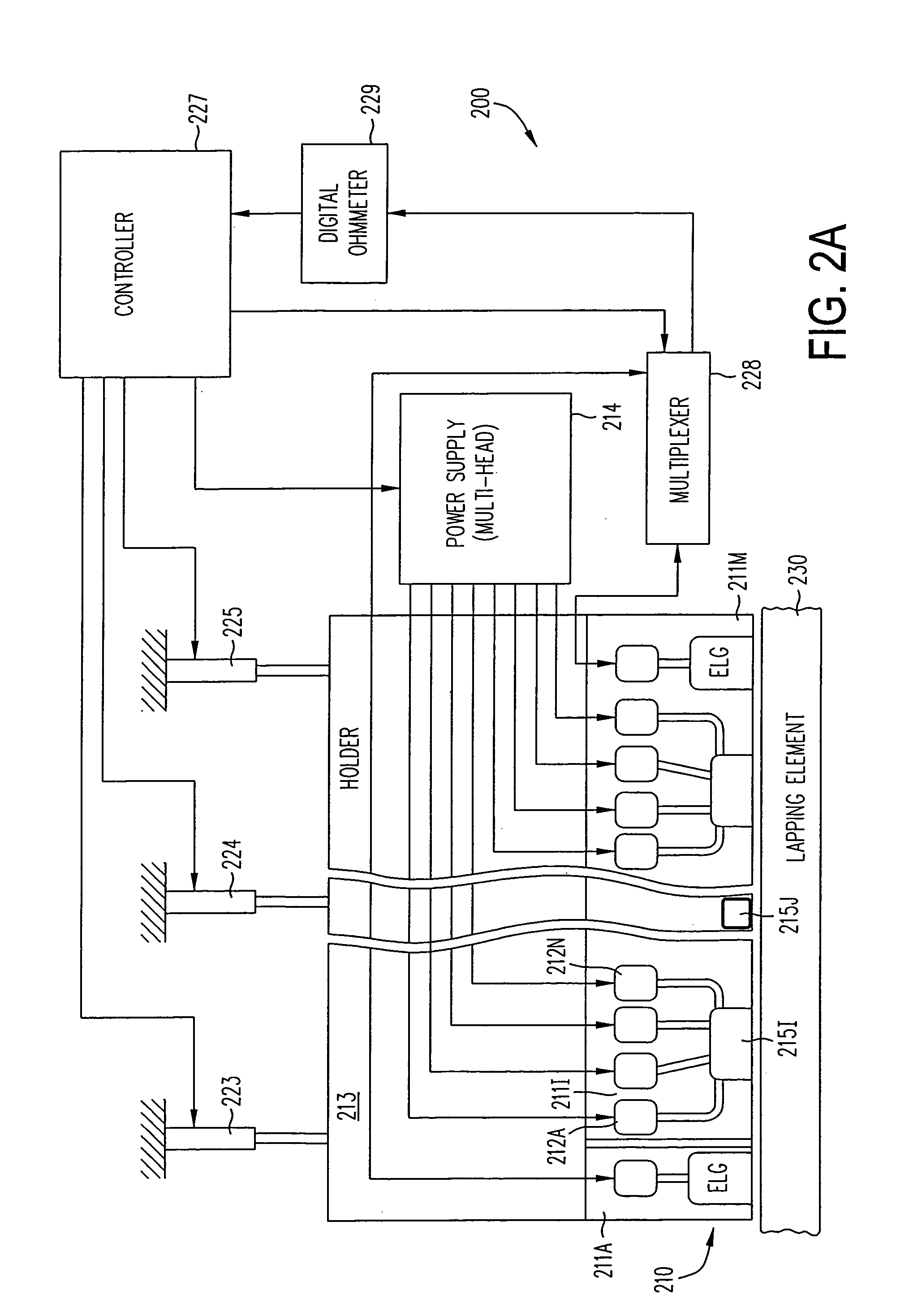
[0041]In one embodiment, a head 211I (FIG. 2A) for a drive (such as a tape drive or a disk drive) is manufactured by photolithography (as per act 251 in FIG. 2B) to have formed thereon a transducer 215I (FIG. 2A) coupled to a number of terminals 212A–212N (FIG. 2A). Depending on the implementation, the photolithography can take 50–100 steps. Transducer 215I may include a magnetoresistive (MR) read element 301 (see FIG. 3A), and optionally a thin film inductive write element and / or copper coils 302 (FIG. 3A). Copper coils 302 are coiled around pole pieces in any manner well known in the art.

[0042]Although certain specific features of one particular example of a head 211I are described herein, any type of head can be powered up during lapping as described herein. Examples of head that can be powered up include Magneto Resistive (MR), Giant Magneto Resistive (GMR), Tunnel Magneto Resistive (TMR), and Current Perpendicular to Plane Magneto Resistive (CPPMR).

[0043]Depending on the embodi...


PUM


Abstract

A head for use in a drive includes a heating element capable of generating heat sufficient to cause the head to have a shape that is similar or identical to the shape that the head has when performing an operation (e.g. writing) on a recording medium in the drive. The heating element is activated when the operation is not being performed. Hence, a head generates the same amount (or similar amount) of heat and is therefore at the same temperature (also called “operating temperature”), regardless of whether or not an operation (such as writing) is being performed. Therefore, the head maintains a fixed shape or has a shape that varies minimally, within a predetermined range around the fixed shape, that in turn results in maintaining fly height (distance between the head and the recording medium). The heating element may be implemented to use loss mechanisms inherent in a write transducer, e.g. by providing a center tap to the write transducer. When using a center tapped write transducer, currents in phase with one another are provided to perform a write operation. When not performing the write operation, the same currents are provided, but out of phase.

Description

CROSS-REFERENCE TO RELATED APPLICATIONS[0001]This application is a continuation-in-part of, and incorporates by reference herein in its entirety the commonly owned and U.S. Patent Application entitled “LAPPING A HEAD WHILE POWERED UP TO ELIMINATE EXPANSION OF THE HEAD DUE TO HEATING” filed by Christopher H. Bajorek and having the application Ser. No. 10 / 158,776 and a filing date of May 30, 2002, now U.S. Pat. No. 6,857,937.BACKGROUND OF THE INVENTION[0002]Expansion of materials at the micrometer scale and nanometer scale is important in data storage devices such as magnetic tape and disk drives. Specifically, such devices contain a small device called a “slider” on which is located a “head”. The slider moves relative to a recording medium (such as a tape or disk) during normal operation. The head contains circuitry (called “transducer”) to perform the functions of reading from and writing to a recording medium 120. A conventional head 110 (FIG. 1A) includes a microscopic region 111 ...

Claims


Application Information

Patent Timeline
IPC IPC(8): G11B5/41G11B5/09G11B5/02G11B5/10G11B5/105G11B5/31G11B5/39G11B5/40G11B5/455
CPCG11B5/10G11B5/105G11B5/3103G11B5/3133G11B5/3136G11B5/3169G11B5/3173G11B5/40G11B5/3106G11B5/3116G11B5/3163G11B5/3967
Inventor BAJOREK, CHRISTOPHER H.O'DELL, THOMAS A.
Owner WESTERN DIGITAL TECH INC
Learn More