System and method for controlling transmitter output levels in a wireless communications device

Inactive Publication Date: 2006-10-10
KYOCERA CORP
View PDF6 Cites 7 Cited by
  • Summary
  • Abstract
  • Description
  • Claims
  • Application Information

AI Technical Summary

Benefits of technology

[0012]The present invention facilitates efficiently stabilizing the output from a transmitter that is operating in a wireless communications device. The effects of

Problems solved by technology

However, the initial transmit bias control values may be subject to substantial inaccuracies, reducing the effectiveness of the initial transmit bias control value and increasing the time delay in stabilizing the transmitter output signal.
For example, variations between transistor lots, ambient operating temperature, battery voltage, transistor junction temperature, and the heatsink (wireless device circuit board) temperature

Method used


Image

  • System and method for controlling transmitter output levels in a wireless communications device
  • System and method for controlling transmitter output levels in a wireless communications device
  • System and method for controlling transmitter output levels in a wireless communications device

Examples


Embodiment Construction

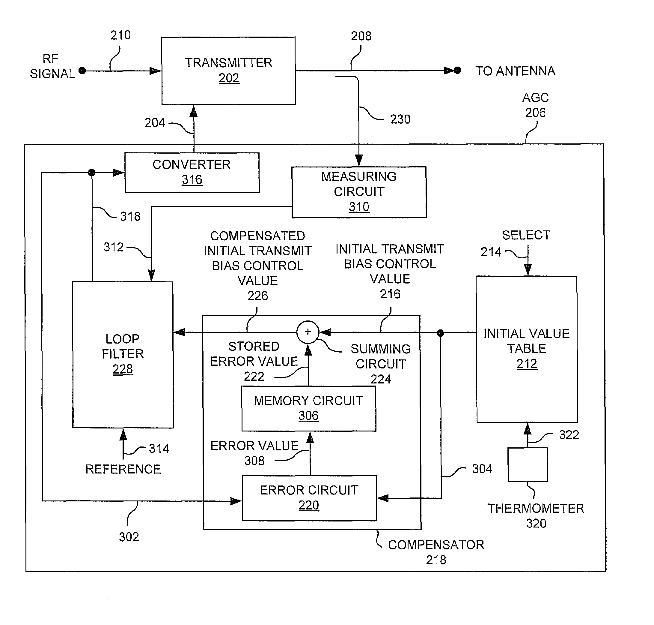
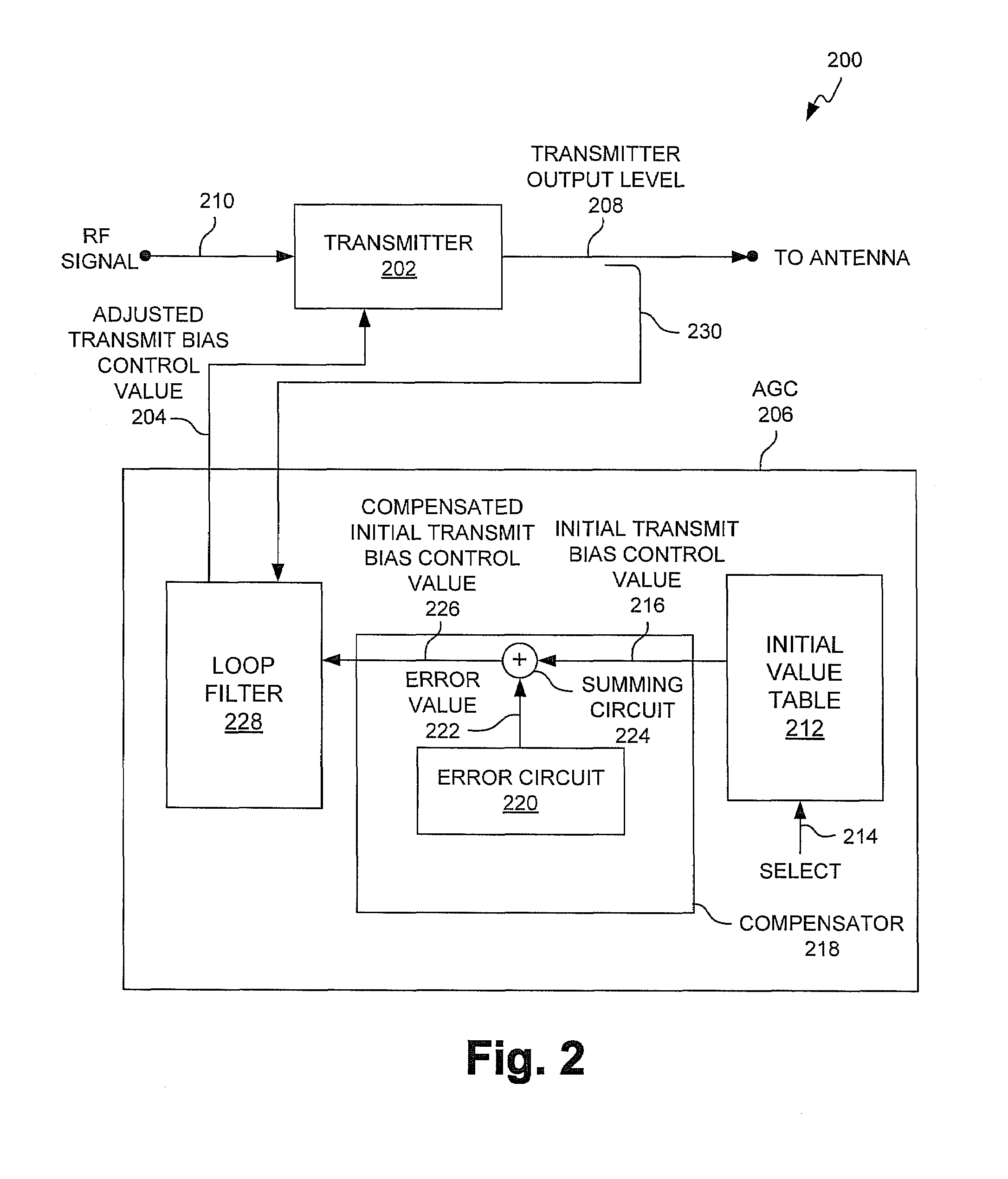
[0020]FIG. 2 is a schematic block diagram of a system 200 for controlling transmitter output levels in a wireless communications device in accordance with the present invention. A transmitter 202 has an input on line 204 accepting a transmit bias control value from an automatic gain control (AGC) circuit 206. The transmit bias control value is used to control the transmitter output level. Transmitter 202 has an output on line 208 supplying a transmitter output level responsive to the transmit bias control value. The transmitter 202 accepts an RF signal on line 210 from previous blocks or circuits (not shown).

[0021]The AGC 206 includes a table 212 of initial transmit bias control values cross-referenced to transmitter output levels. Wireless communications devices, such as wireless telephones, operate at specified and controlled transmitter output levels. Accordingly, table 212 has an input to accept transmitter output level selections on line 214 and an output supplying initial tran...


PUM


Abstract

A system and method are provided for controlling transmitter output levels in a wireless communications device. The method comprises: maintaining a table of initial transmit bias control values cross-referenced to transmitter output levels; selecting transmitter output levels; supplying an initial transmit bias control value from the table corresponding to a selected transmitter output level; generating an initial transmitter output level; measuring the transmitter output level; creating an adjusted transmit bias control value in response to the measured transmitter output level, and to a reference value; using the difference between the initial transmit bias control value and the corresponding adjusted transmit bias control value to create an error value; saving the error value; and adding the error value to a subsequent initial transmit bias control value.

Description

BACKGROUND OF THE INVENTION[0001]1. Field of the Invention[0002]This invention generally relates to automatic gain control (AGC) circuits and, more particularly, to a system and method for compensating the error in voltage values used in biasing an advanced mobile phone service (AMPS) wireless communications device transmitter.[0003]2. Description of the Related Art[0004]The output signal from transmitter circuitry, such as a power amplifier used to transmit signals in a wireless communications device, is inherently sensitive to changes in temperature, operating frequency and lot variations. As a result, it is well known to employ an AGC circuit to adjust the transmitter output level for more accurate output. In an AGC circuit, typically the transmitter output level is sampled and converted into a dc voltage, with the dc voltage used to set a feedback signal to adjust the output level from a power amplifier.[0005]FIG. 1 is a schematic block diagram of a conventional transmitter with...

Claims


Application Information

Patent Timeline
IPC IPC(8): H04B1/04H03G3/30H04B7/005
CPCH03G3/3042H04W52/50
Inventor VAIDYANATHAN, REMASRINIVAS, GUDA
Owner KYOCERA CORP
Why Eureka
Try Eureka