System and method for steering directional antenna for wireless communications

Active Publication Date: 2006-10-10
TEXAS INSTR INC
View PDF4 Cites 28 Cited by
  • Summary
  • Abstract
  • Description
  • Claims
  • Application Information

AI Technical Summary

Benefits of technology

[0009]The present application describes a system and method for determining the optimal antenna position (pointing angle and/or azimuth and/or elevation angle) of a directional antenna in a wireless communication system by computing a steering metric (SM) at each of a multiplicity of antenna positions. This steering metric is a function of receiver gain G (indirectly measur

Problems solved by technology

Operating range in a wireless system typically decreases with increasing data rate, for a given transmit power (which is often l

Method used


Image

  • System and method for steering directional antenna for wireless communications
  • System and method for steering directional antenna for wireless communications

Examples


Embodiment Construction

[0014]The description that follows presents a series of systems, apparati, methods and techniques that facilitate additional local register storage through the use of a virtual register set in a processor. While much of the description herein assumes a single processor, process or thread context, some realizations in accordance with the present invention provide expanded internal register capability customizable for each processor of a multiprocessor, each process and / or each thread of execution. Accordingly, in view of the above, and without limitation, certain exemplary exploitations are now described.

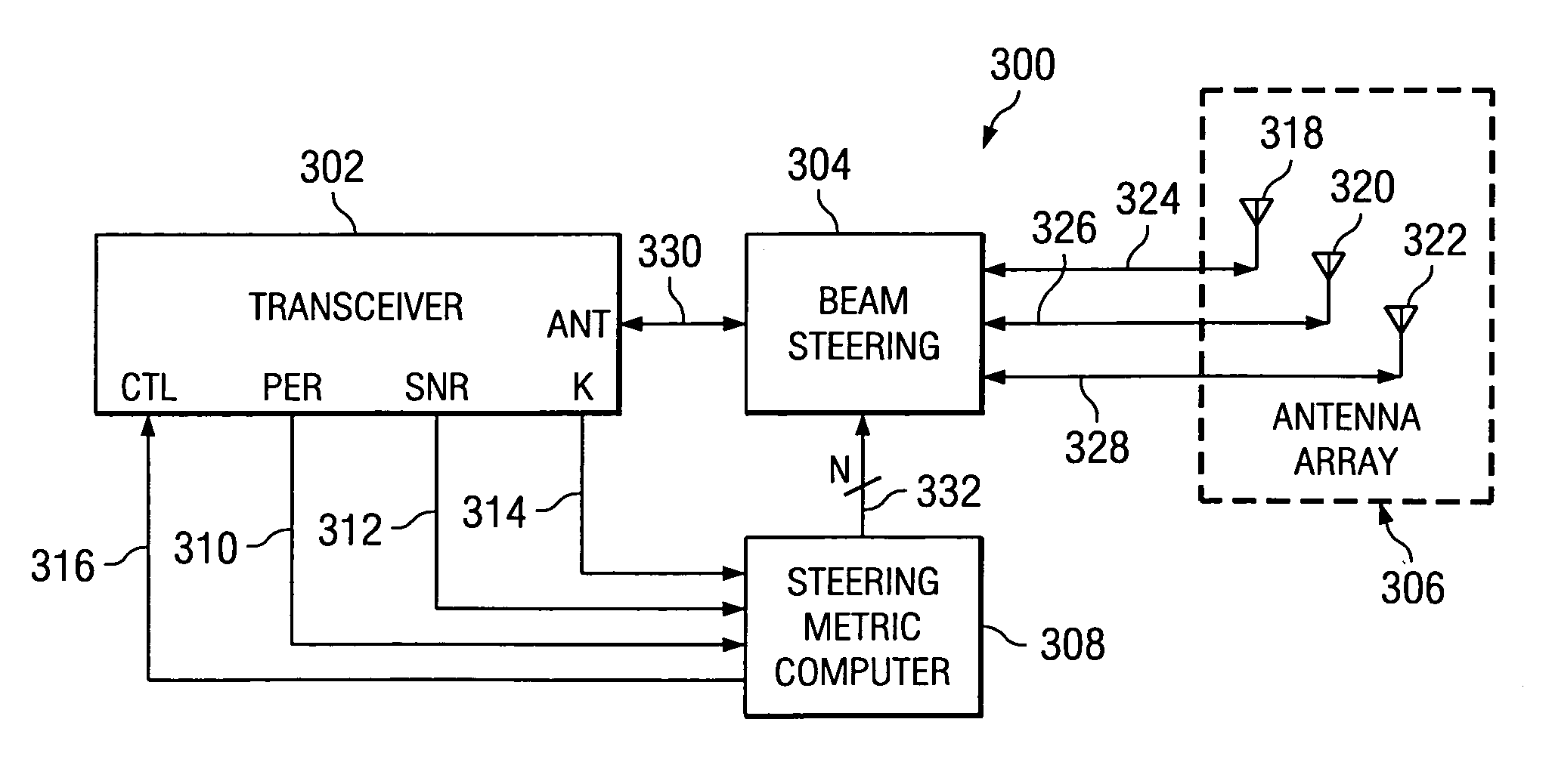
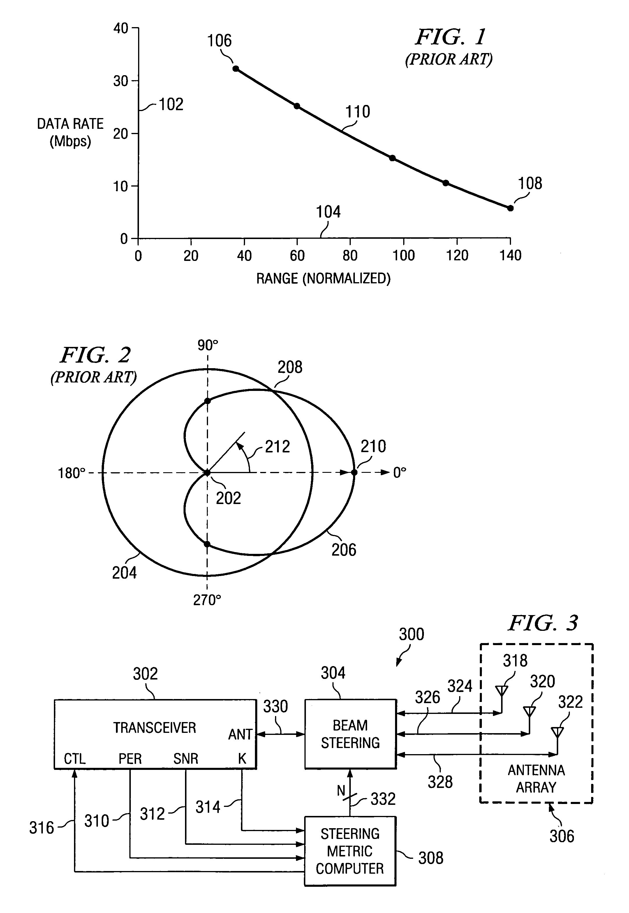
[0015]FIG. 1 is a graph of the known general relationship between data rate and range in a typical 802.11 WLAN system. The vertical axis 102 represents data rate in Mbps; the horizontal axis 104 represents a dimensionless measure of relative distance. Actual distance achieved is dependent on many factors other than data rate, such as transmit power, obstructions in the path, interfer...


PUM


Abstract

A system and method for determining an optimal antenna position of a directional antenna in a wireless communication system are described. The optimal antenna position is determined by calculating a steering metric value for possible antenna positions and the antenna position with the highest steering metric value is selected as the optimal antenna position.

Description

BACKGROUND[0001]1. Field of the Invention[0002]The present disclosure relates to wireless data communication in general, and, in particular, to wireless data communication systems using switched-beam or other directional antenna technology, and the computation of a steering metric (SM) to enable optimization of antenna position (antenna pointing direction).[0003]2. Description of the Related Art[0004]Wireless data communications systems enable data transmission among two or more network elements. An example is a wireless local-area network (WLAN) system, widely used for connecting network elements in homes and offices, based on IEEE standard 802.11x (data rates from 6 to 54 Mbps). Operating range in a wireless system typically decreases with increasing data rate, for a given transmit power (which is often limited by law). Typical wireless network elements such as a WLAN access point (AP) use omni-directional antennas for receiving and transmitting data because network elements typic...

Claims


Application Information

Patent Timeline
IPC IPC(8): H04M1/00H04B1/00H04B7/00H04B7/14H04J99/00
CPCH01Q3/2605
Inventor WILHOYTE, MICHAEL E.GOETTEMOELLER, MICHAEL V.
Owner TEXAS INSTR INC
Why Eureka
Try Eureka