
Buried line locator with integral position sensing

a technology of position sensing and locators, applied in the field of electronic devices, can solve the problems of damage to the line, serious injury to a person excavating near the line, and incorrect determination of the location of the lin

Active Publication Date: 2006-10-10
BUSAN TRANSPORTATION CORPORATION
View PDF13 Cites 115 Cited by
  • Summary
  • Abstract
  • Description
  • Claims
  • Application Information

AI Technical Summary

Benefits of technology

"The present invention provides a line locator that can accurately measure the strength of the electromagnetic field emanating from a target line. The line locator has a receiver that measures the field, an accurate spatial locator to determine its position, and a processor to record the data. The mapping of the field strength as a function of position can be used to locate underground lines and determine their physical location. The accurate spatial locator can use an inertial mapping system or a triangulation mapping system to determine the position of the receiver. The line locator can also use a range-finder, such as a laser, to determine its position. Overall, the invention provides a more accurate and efficient way to locate underground lines and their surrounding structures."

Problems solved by technology

However, there are situations in which the use of a line locator can result in the improper determination of the location of the line, which can result in damage to the line or serious injury to a person excavating near the line.
A distorted field can result in an incorrect determination of the location of the line as well as an inaccurate measurement of depth.
The problem with the use of GPS for this purpose is that the accuracy of GPS or even Differential GPS (DGPS), is not generally sufficient.
This accuracy is not sufficient for dealing with distorted electromagnetic fields from underground lines.
Although some embodiments of GPS provide an accuracy of less than one inch, these measurements cannot be made in real time as the receiver of the locator is moved at reasonable rates spatially over the area of interest.
Another problem in the field of underground line location is the need to keep track of the position of buried lines over periods that last more than a few hours or days.
However, it is often necessary to locate the lines with respect to landmarks in the vicinity of the lines in the event that the paint wears away or is moved.
Tape measures used in this fashion do not provide the required level of accuracy.
Further, the length of time required to obtain accurate positional data for line locator measurements using a tape measure is generally prohibitive.

Method used


Image

  • Buried line locator with integral position sensing
  • Buried line locator with integral position sensing
  • Buried line locator with integral position sensing

Examples


Embodiment Construction

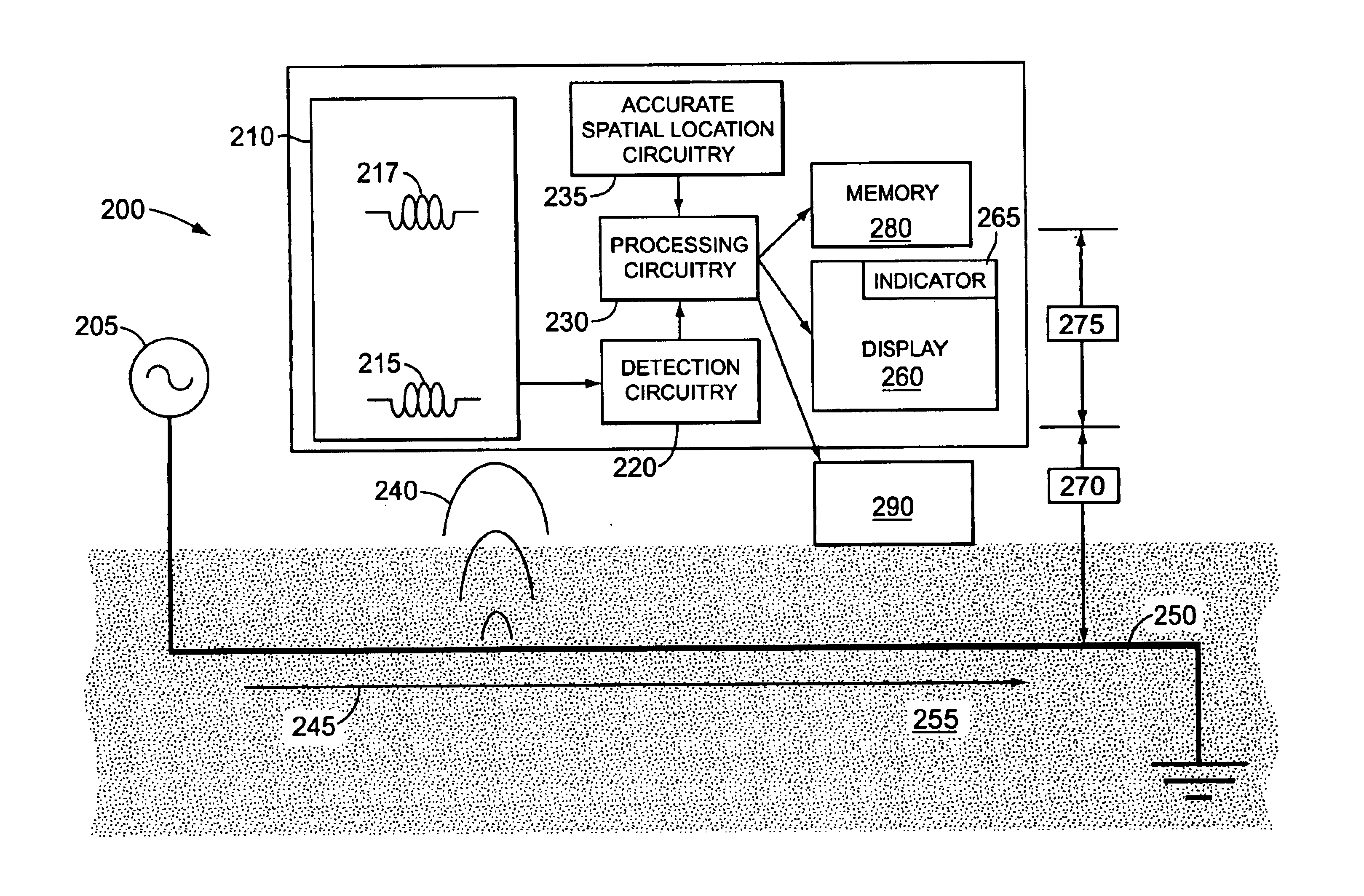
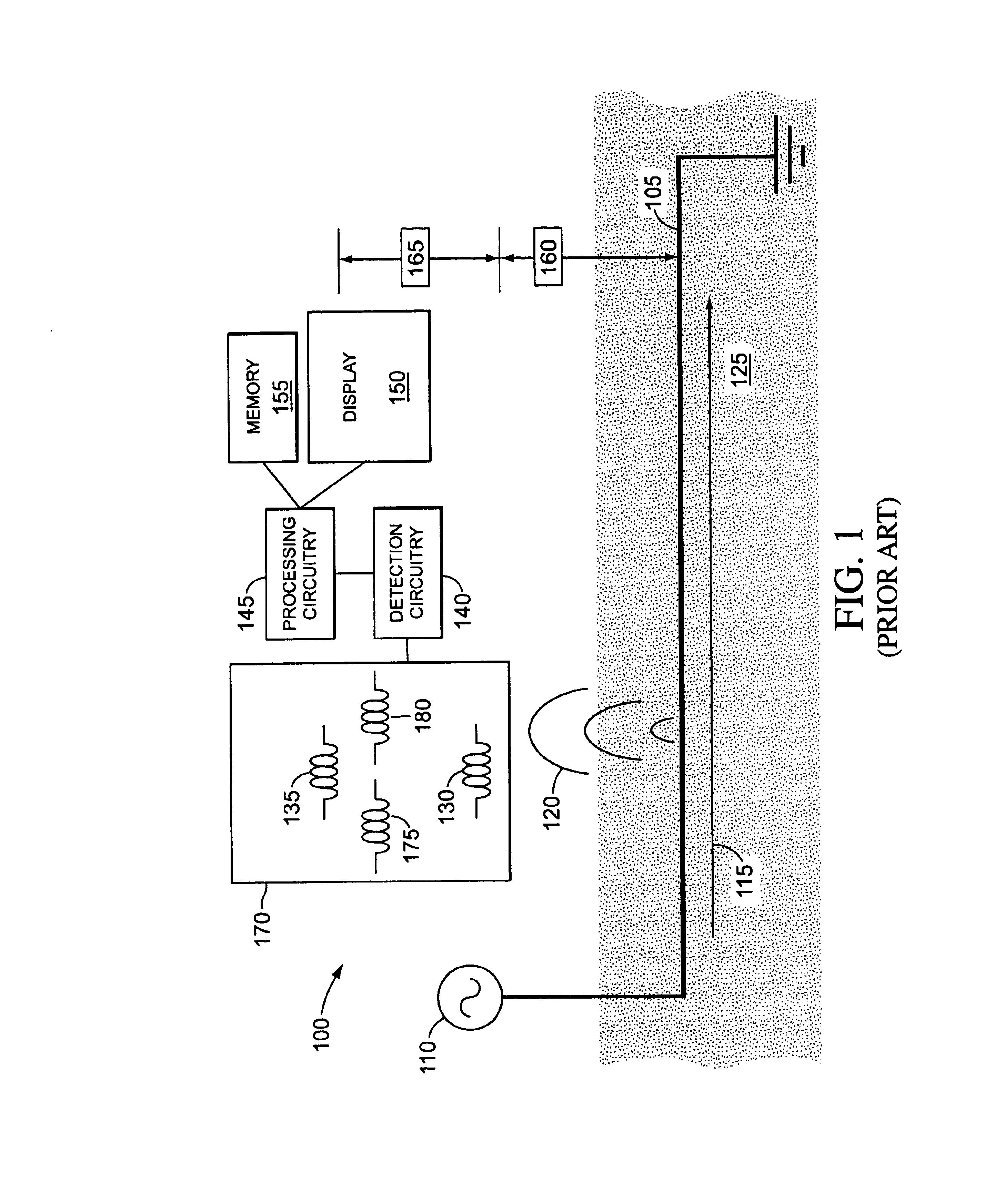
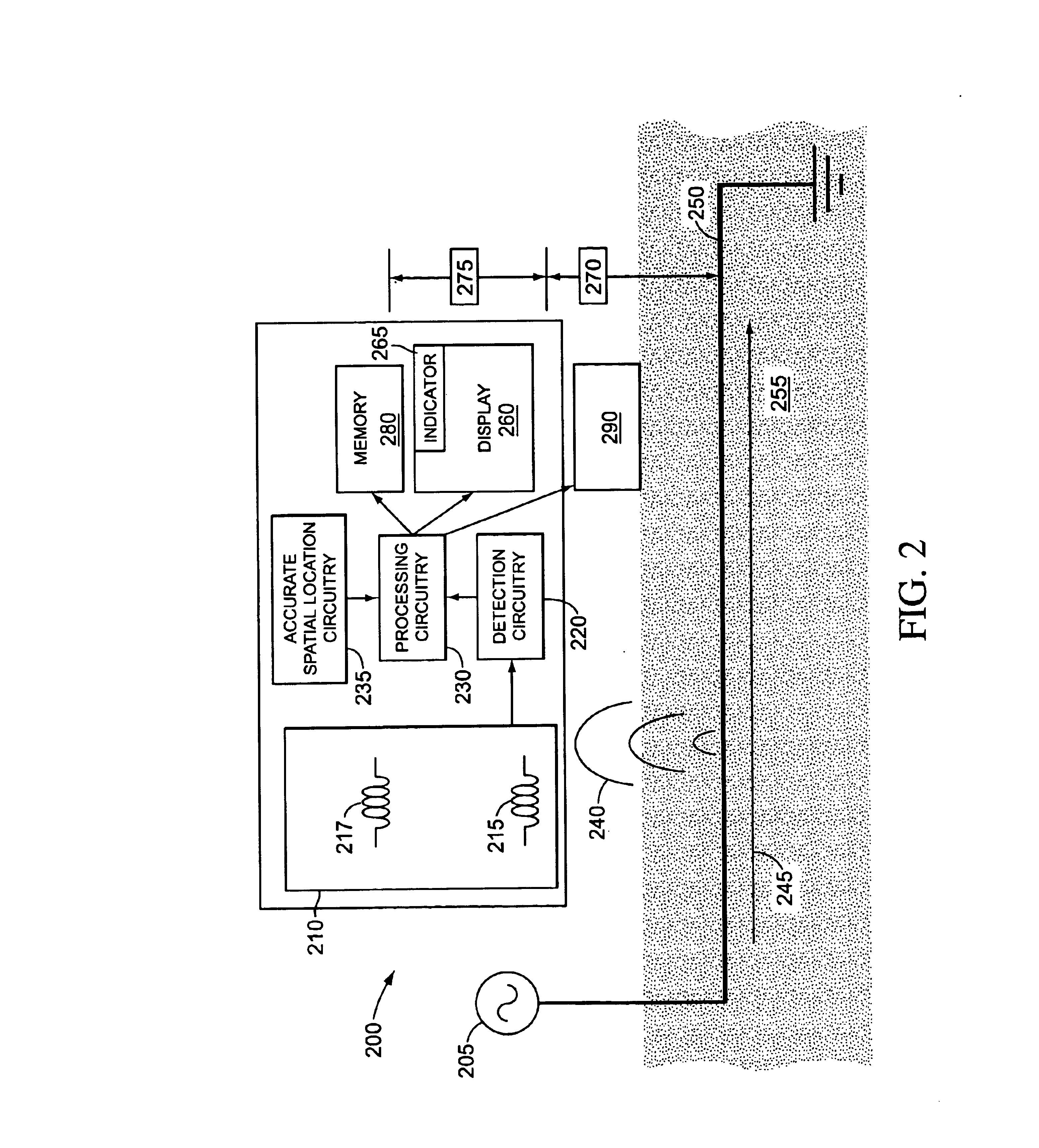
[0028]FIG. 1 shows a schematic diagram of a conventional line locator system 100 positioned above a line 105. Transmitter 110 can be coupled to line 105 in order to induce current 115 to flow through line 105. As current 115 flows through line 105, it generates electromagnetic field 120 that is radiated from line 105. If current 115 is constant, electromagnetic field 120 is a static electromagnetic field. If current 115 is time varying, electromagnetic field 120 is also a time-varying electromagnetic field. A portion of the electromagnetic field 120 penetrates ground 125, where it can be detected by receiver 170 of line locator 100. In the embodiment of locator 100 shown in FIG. 1, receiver 170 includes detectors 130, 135, 175 and 180, which can be positioned to determine both the depth of line 105 and the lateral position of line 105.

[0029]Transmitter 110 is shown in a direct connection mode, i.e. transmitter 110 is electrically coupled to line 105. The electrical connection can, f...


PUM


Abstract

A device for detecting and compensating field distortion in underground line locators by means of mapping the field-strength of the field generated by electrical currents within the buried line. Signals from the underground structure can be mapped with respect to the position of the device. From the map, distortions from the expected signals can be determined, indicating interference from other structures or errors in detected location of the structure.

Description

BACKGROUND[0001]1. Field of the Disclosure[0002]This disclosure relates to the field of electronics and, in particular, to the application of devices that can be used to locate objects that are concealed or situated underground.[0003]2. Related Art[0004]Line locators are used to locate the position of lines buried in the ground, such as gas pipes, water pipes, telephone cables, and power cables. A line locator typically includes a transmitter and a receiver. The transmitter causes an electromagnetic field to be radiated from the line to be located. The receiver locates the line by detecting the radiated field. Line locators may be operated in one of two modes, a direct connection mode and an inductive mode.[0005]In direct connection mode, the transmitter is physically connected to the line to be located, typically at a point in the line that is above the ground. The transmitter generates a voltage at one end of the line, causing an electrical current to flow along the conductive lin...

Claims


Application Information

Patent Timeline
Patent Type & Authority Patents(United States)
IPC IPC(8): G06F19/00G01V3/00G01V3/08
CPCG01V3/08
Inventor PACEY, GORDON
Owner BUSAN TRANSPORTATION CORPORATION
Learn More